
No model number gotta shoot from the hip on this one:
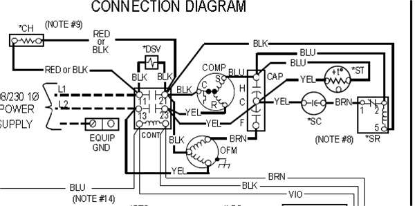
The cap has 3 sections: Herm for compressor, F for fan, and C for common.
The common section of the cap gets a hot wire off the power cord, a wire from compressor marked C on compressor and a white common wire from the fan gets connected to C on that cap. These wires are almost always white in color on American OEM. The fan has a small brown wire that connects to F on tha cap. The compressor has a wire marked S on it make a note of that color wire and connect it to the section on the cap called HERM. Herm stands for hermedtically sealed compressor. So both your commons and a hot wire go to C. You need one small brown wire which goes to F from the fan. One wire marked S on the compressor goes to Herm for compressor starting. S stands for start winding.
Lets look at typical American fan motor wires: The fan has a black wire for high speed a blue wire for medium and a red wire for low. It has white wire for common, and a brown wire for capacitor. Connect your common fan wire to common and the brown wire to F.
With that cap properly connected basically all you would need to do to make it run is connect a fan speed, the compressor wire marked R for RUN, and and the other power wire. 
If you need further help, reach me via phone at https://www.6ya.com/expert/dan_73bbd84fe1d95b61

SOURCE: need a wiring diagram for capacitor on carrier ac
see page 2 here...the drawing section with H (hermetic compressor) F (fan) and C (common. -- http://www.docs.hvacpartners.com/idc/groups/public/documents/techlit/38en-1w.pdf

4,196 views
Usually answered in minutes!


×