Foxconn 661M03-G-6EL Motherboard Logo

Related Topics:

Posted on Jul 25, 2008
Answered by a Fixya Expert

Trustworthy Expert Solutions

At Fixya.com, our trusted experts are meticulously vetted and possess extensive experience in their respective fields. Backed by a community of knowledgeable professionals, our platform ensures that the solutions provided are thoroughly researched and validated.

View Our Top Experts

Foxcon Motherboard pinout

Hi, I need to know the Pinout for the Power SW, Reset SW, HDD SW and the Power LED on a FOXCON Motherboard PC 661M03-G-6EL this is in an Enpower Computer

Thank You

1 Answer

Anonymous

Level 3:

An expert who has achieved level 3 by getting 1000 points

All-Star:

An expert that got 10 achievements.

MVP:

An expert that got 5 achievements.

President:

An expert whose answer got voted for 500 times.

  • Master 2,351 Answers
  • Posted on Jul 27, 2008
Anonymous
Master
Level 3:

An expert who has achieved level 3 by getting 1000 points

All-Star:

An expert that got 10 achievements.

MVP:

An expert that got 5 achievements.

President:

An expert whose answer got voted for 500 times.

Joined: Dec 04, 2007
Answers
2351
Questions
3
Helped
1591004
Points
6609

Hi bwalker24,
This is a pic of how to connect you're LED & switches.
Foxcon Motherboard pinout - f0649db.jpg Enjoy!

Mike

Add Your Answer

×

Uploading: 0%

my-video-file.mp4

Complete. Click "Add" to insert your video. Add

×

Loading...
Loading...

Related Questions:

2helpful
2answers

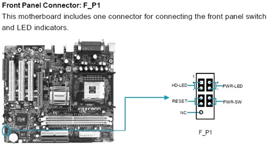
Front panel connections

I don't find the Front Panel header pinout online, nor do I have an MSI MS-5191 in the shop.

I would suggest using one the LED lights with two wires.
(3-wire is a dual color LED)

There are two rows of pins. Usually the Power On switch, Power On LED, and Speaker; are on the same row.
HarDDrive activity LED, and Reset Switch are on the opposite row.

Speaker has 4-pins designated for it. All the others use 2-pins.
(Unless the PWR ON LED is a dual color jobbie)

Touch two pins next to each other, in the same row; with the 2-wire LED.
Start with finding the Power On switch first.

Usually the top row 1st two pins are Power On LED (Light)
Next in line are the 2 pins for the Power On switch.
Bottom row 1st two pins are usually HarDDrive activity LED (light)
Next 2-pins are usually Reset switch.

May not apply to a motherboard old enough to use a Socket 7 processor socket.
There may be 18 to 20-pins.
Bear in mind that many are not used, and probably 4 are for an internal speaker, for hearing BIOS Beep Codes.
May be two separate Front Panel headers.

Once you find the two contact pins in the Front Panel header, for the Power On switch; I would put the Power On switch wires on.
The small pin connector on the wire/s, will keep you from accidentally touching these two pins again, when the computer is on.

Now you have the two pins for the Power On switch, and the computer is running; then keep touching 2-pins at a time with the LED. (Light Emitting Diode)

LED stays on? You have the Power On LED (Light) pins.
LED blinks? HarDDrive activity LED (light) pins.
Computer restarts? Reset switch pins.

Look for abbreviations near the pins in the Front panel header.

PWR, Pwr, Pwr On, Sw, and SW; are just some of the abbreviations for the Power On switch.

HDD LED, and HDD are two for the HarDDrive activity LED. (Light)
(If it states HDD SW it is the Power On switch. Weird old way of marking)

RST, Reset, and RSW, are for the Reset Switch.
(Reset Button)

If you see 4 pins marked with a bracket ( [ -> Turn so it's horizontal), these are for the internal speaker.

Type MSI front panel connector in your search bar, and look at -> images. See if you can find an image of your MSI Front Panel header pinout.

You can bet MSI carried out that Front Panel header pinout, on other MSI motherboards, besides the MS-5191.

The MSI MS-5191 may have been a motherboard made by MSI, especially for a pre-built computer manufacturer, and not listed on their website as an OEM motherboard.
(Original Equipment Manufacturer)

Won't have the Front Panel header pinout, listed on MSI's support website. (Doesn't)
But you can bet there IS an OEM motherboard made by MSI, that the Front Panel header DOES match.

May be different expansion slots, or motherboard chipset, or whatever; but the same Front Panel header pinout.

Regards,
joecoolvette
0helpful
1answer

Reconnect the HDD LED, PWR LED, PWR SW, RESET SW

You pretty much need a flashlight and a magnifying glass to have a look see at the header on the motherboard. The pinout is printed on the board in _very_ small print. The LED's are the only ones that require polarity to work. Connecting the wires wrong won't hurt anything...it just won't work the way it is supposed too. A little trial and error may be in order.
Another, more accurate solution, is to go the manufacturer's website for that computer and download the user manual. The pinout will be in the manual, usually under "front panel connections".
0helpful
1answer

TRYING TO HOOK UP MU POWER BUTTON NEED TO KNOW

Hi there
The front panel connectors are mainly,
  • harddisk activity connector
  • power switch connector
  • reset switch connector
  • power LED connector
  • speakers connector
  • USB connector
Harddisk activity connector
This normally comes red in colour and is labeled as HDD-LED
Power switch connector
This comes green in colour and is labeled as POWER-SW
Reset switch connector
This usually comes grey in colour and is labeled as RST-SW
Power LED connector
This is usually green in colour and is labled as PWR-LED
Speakers connector
This speaker will give different beep sounds during boot to tell the user if there is any errors. It occupies 4 pins, however only 2 is important for the function. Be sure to connect the red coloured cable to the positive polarity and the black to the negative.
front_panel_connectors.jpg Front panel connectors pins on the motherboard
front_panel.jpg Front panel connectors from the casing

Good luck and thanks for using FixYa!!

3helpful
1answer

I need the front panel pinout for an Emachine T2984 motherboard

Here is the pinout for several Intel MB's with 845GV Chipset.

b083e02.jpg
15helpful
1answer

IBM Netvista MB 49p1599 Front Panel Pinout

1 pw sw
2 pw sw
3 rst
4 rst
5 - pw led
6+ pw led
7+ hdd led
8 - hdd led
<== left 1. . . . . .8
ATX connector ==> right
1helpful
2answers

P4VMM2 motherboard

You can download the manual from here (Europe) or here (US).
11helpful
1answer

Foxconn motherboard pinout

Please follow this link and download the manual.

http://www.foxconnchannel.com/support/downloads_detail.aspx?ID=en-us0002117

Don't be surprise that the manual name is 662M03, it is still the right manual becuase is made for both type of motherboards.

96b89ec.jpg
2helpful
1answer

PC Chips M955G Motherboard Front Panel Pinout

i suggest to find in website..www.Fixya.com
if not found..post it again so that we can suggest another site.

thanks
0helpful
1answer

Pinout diagram

Mail sent.

For anyone else.. Visit the motherboard's online manual via their website.
Not finding what you are looking for?

1,801 views

Ask a Question

Usually answered in minutes!

Top Foxconn Computers & Internet Experts

Jose Ramirez

Level 2 Expert

264 Answers

Mohammad Abumuailek
Mohammad Abumuailek

Level 2 Expert

104 Answers

Grand Canyon Tech
Grand Canyon Tech

Level 3 Expert

3867 Answers

Are you a Foxconn Computer and Internet Expert? Answer questions, earn points and help others

Answer questions

Manuals & User Guides

Loading...