1995 Lexus ES 300 Logo

Related Topics:

r
ray fulton Posted on Mar 23, 2018
Answered by a Fixya Expert

Trustworthy Expert Solutions

At Fixya.com, our trusted experts are meticulously vetted and possess extensive experience in their respective fields. Backed by a community of knowledgeable professionals, our platform ensures that the solutions provided are thoroughly researched and validated.

View Our Top Experts

Can someone help me with a 1995 lexus es300 3.ol v6 vacuum hose reconstruction

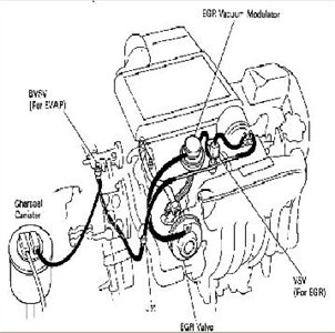
I removed the top intake manifold and can't remember the hose configuration please help

1 Answer

toddgilbert

Level 3:

An expert who has achieved level 3 by getting 1000 points

Top Expert:

An expert who has finished #1 on the weekly Top 10 Fixya Experts Leaderboard.

Superstar:

An expert that got 20 achievements.

All-Star:

An expert that got 10 achievements.

  • Lexus Master 6,360 Answers
  • Posted on Mar 23, 2018
toddgilbert
Lexus Master
Level 3:

An expert who has achieved level 3 by getting 1000 points

Top Expert:

An expert who has finished #1 on the weekly Top 10 Fixya Experts Leaderboard.

Superstar:

An expert that got 20 achievements.

All-Star:

An expert that got 10 achievements.

Joined: Sep 07, 2017
Answers
6360
Questions
5
Helped
1523966
Points
27737

I recently tried the DIY service and repair manuals from a website and it actually helped me repair transmission problem in my jcb 3cx site-master. it wont move forward or reverse, engine is good both solenoids for forward and reverse work.

I don't have much technical knowledge but I just followed it step-wise, and works perfect! got it from www.reliable-store.comAll the best

5 Related Answers

Anonymous

  • 123 Answers
  • Posted on Sep 15, 2008

SOURCE: Where is the vacuum hose

IF the engine was revving high RPMS it had to be a serious vaccum leak. If the PCV came undone it would cause it rev up quite high. the shaking was from the factory set RPM limiter when not in gear (around 4,000 RPMS) the only other vaccum leak big enough would be for the brake booster. They both have a check valve but that doesn't mean much. I would start there PCV is around 5 bucks and the other is about the same. If you need pics of location I could do that also.

Ad
inf12

Harry Daehling

  • 13 Answers
  • Posted on Feb 08, 2009

SOURCE: intake manifold vacuum line

THIS IS FOR TURBO ENGINE
13b2405.jpg NON TURBO ENGINE
6781864.jpg

Anonymous

  • 17 Answers
  • Posted on Feb 23, 2009

SOURCE: intake manifold cover

remove oil cap steam an it should just lift off

Anonymous

  • 1 Answer
  • Posted on May 16, 2009

SOURCE: vacuum leak

mine is doing the same, it's your pcv receptor on the manifold. that hard plastic cover is actually part of the intake itself, if it "came off" it would cut your intake in half. that seem seals the two halfs together. you gotta pull the whole intake off and replace it... or jimmy rig it.

Anonymous

  • 507 Answers
  • Posted on Oct 28, 2009

SOURCE: need diagram of vacuum hoses for 1993 ford

you need to change the modulator on the trans as its vacuum controlled and itsdamaged letting auto fluid get sucked up the line,(diaphragm probably split in modulator

Ad

Add Your Answer

×

Uploading: 0%

my-video-file.mp4

Complete. Click "Add" to insert your video. Add

×

Loading...
Loading...

Related Questions:

0helpful
1answer

I have a 2001 Mazda Tribute V6 3.0 and I'm trying to find were the pulse damper vacuum hose connects to? Please help.

The pulse damper vacuum hose on a 2001 Mazda Tribute V6 3.0 connects to the intake manifold. Look for a small vacuum hose coming from the pulse damper and follow it to the intake manifold. The intake manifold is typically located on the top of the engine and will have a series of hoses and cables connected to it. The pulse damper is typically located near the fuel injectors and fuel rail. Make sure the hose is connected securely and in good condition, as any leaks or damage can cause issues with the engine's performance.
0helpful
2answers

Where is the thermostat in my 95 Isuzu rodeo 3.2 ltr. V6

where is such a simple word
where;
3.2L V6, SOHC head 6VD1 (not the 6vd1w twin cam heads)
x marks the spot
asked many time here, and same answer.
if you look , you see it, then see its not possible to get to the 2 rear bolts (telling you what?)
pull engine block, ? no
pull intake, yes.

here-bp54dlzlp0pmj5fwzd335nwr-4-0.jpg
0helpful
1answer

2005 escape 3.0 V6, disconnected battery lead, removed upper intake manifold to replace spark plugs bank 1. Replaced manifold and all hoses, reconnected battery. Now transmission has slow shift.

check that you replaced the vacuum hose from the manifold to the actuator on the transmission
check that you have not caught it under the manifold and pinched it
1helpful
1answer

I need to replace the intake and carb on a 460 E350 engine. Looking for any and all help or tips and tricks as possible! This is my first time doing this so I basically a DIY for dummies. I wish there was...

Intake manifold and carb replacement. I will try to walk you through this from memory as its not that hard.
  • Remember to replace gaskets for carb, intake and related components like egr valve etc.
  • Loosen and remove fuel lines, electrical connections, vacuum hoses etc that are either in the way, or connected to the manifold itself. Unhook the battery to make sure there aren't any unexpected sparks. The more room you provide yourself the better, remove radiator hoses/thermostat housing from intake.
  • Loosen the distrubter cap and set aside, try not to remove the plug wires, if you do, take note of where they go. take note of the position of the rotor button, might want to place a mark with chalk or fingernail polish on the dist. to mark the rotor position. Lift out the distrubuter using a twisting motion. (goes back in same way with twisting motion, if rotor is not lined up, remove and try again, you might get away with it being close, as you can adjust dist. to put it exactly back in time during install, but this will be much later)
  • remove the carb and linkage, and all carb related springs and hoses, mark or remember locations.
  • with dist. and cap out of the way, and all electrical connectors off or out of the way, and vacuum hoses removed or out of the way, and with carb removed, remove the bolts holding manifold to engine. Genlty pry the intake up and off of the engine. it may seem stuck. Pry it loose make sure not to gouge or deform any mating surfaces like your heads.
  • Now you have carb and manifold removed. Installation is reverse of removal, but make sure to clean off all the old gasket material from the heads.
Here is a picture you might use to help see what needs to be removed, basically everything on top of engine.
f3b94d7e-cc24-4215-98dc-cc599d5ce4b5.jpg

Sometimes on smog/emissions engines I found that there is some sort of pollution device in the rear between the exhaust manifolds that comes up behind the intake manifold and is connected, eventually by hose, to what I believe is an air pump. The hard metal tubing is between the oil pressure sensor and manifold and doesn't have any play to move it out of the way, in this case i just saw off the stud to gain enough room to remove the manifold.
0helpful
1answer

Replace no 3 coil

if im not mistaken the number 3 coil is on the right hand side of the motor so you will need to remove the intake manifold to gain access to it.
Intake Manifold Removal
  1. Remove the engine cover (if equipped).
  2. Remove the air filter outlet pipe.
  3. Remove the positive crankcase ventilation hose.
  4. Remove the air cleaner resonator.
  5. Disconnect the throttle body electrical connectors.
  6. Disconnect the electrical connectors.
  7. Detach the vacuum hoses.
    • Press the retaining ring. (1)
    • Detach the vacuum hose. (2)

  8. Disconnect the vacuum hose.
  9. Detach the injector harness electrical connector from the intake manifold support bracket.
  10. Remove the intake manifold support bracket.
  11. Detach the engine wiring harness bracket.
  12. Detach the intake manifold support bracket.

    NOTE: Remove and discard the O-ring seal.
  13. Detach the throttle body.
    • Remove the retaining bolts.
  14. Remove the intake manifold.
    • Remove and discard the intake manifold gaskets.
0helpful
1answer

Rusted ERG Valve unit on 1995 F150 How to remove.

Disconnect the negative battery terminal. Disconnect the wiring connectors to the air cleaner, Mass Air Flow sensor, EGR vacuum solenoid, and DPFE sensor. Remove the air intake assembly (up to the throttle body). There are two vacuum lines from the EGR vacuum solenoid, find where they reach the EGR valve and the intake manifold, disconnect them at these points. There is a rubber hose coming from the firewall to the top of the engine, disconnect this and push it aside. Remove the nut directly below this hose (this nut holds the bracket that the DPFE and EGR vacuum solenoid are mounted to). Follow the mounting bracket around and remove the smaller nut holding it on. Have some tape ready to mark two hoses. Make a note of which hose is the "Hi" and "Ref" on the DPFE sensor and remove them. Remove the DPFE/EGR vacuum solenoid assembly. Congratulations, now you have access to the EGR valve!!

hoping help you!
3helpful
1answer

How to replace a starter on a 1991 lexus ls 400

On Lexus ls 400 the starter is located underneath the manifold of intake. The intake manifold has to be removed to replace the starter.The intake manifold located on the top, left side of the engine from the front, along with the hoses, wires and tubes connected to the manifold.Mark each connections before disconnecting.This will help you while reconnecting.The starter is fitted by bolts.Remove the bolts and detach electrical cables on starter.Remove starter from engine compartment.Then re-fit the new starter in reverse as you removed the old starter.Its not very easy job.You will require proper tools to do this.This will help.Thanks.Helpmech.

0helpful
1answer

Where do I find the EGR valve on a 1995 subaru Legacy 250T automatic

  1. Detach the vacuum hose from the EGR valve.
  2. Remove the two nuts which secure the EGR valve to the intake manifold assembly.
  3. Remove the valve and gasket from the manifold.
  4. Clean all gasket material from both mating surfaces.
  5. Check the vacuum hose for deterioration and replace as necessary.

To install:

  1. Inspect the exhaust gas passages in the intake manifold and clean as necessary. Clean the EGR valve assembly as necessary.
  2. Using a new gasket, install the EGR valve.
  3. Tighten the EGR valve securing nuts to 17-19 ft. lbs. (22-25 Nm).
  4. Install the hose on the EGR valve.f9ec12f.gif
2helpful
1answer

Picture of egr valve and were it is located

dffc43b.jpg

Fig. 11: EGR valve and component mounting-3.0L engine


da251ab.jpg

Fig. 12: EGR valve and component mounting-3.8L engine

Removal:
  1. Disconnect the negative battery cable.
  2. If necessary, remove the air inlet tube from the throttle body and air cleaner housing.
  3. Label and detach all vacuum hoses from the EGR valve.
  4. Label and detach any electrical wiring harness connectors from the EGR valve.
  5. Disconnect the EGR valve-to-exhaust manifold tube from the EGR valve.
  6. Remove the EGR valve mounting fasteners, then separate the valve from the upper intake manifold.
  7. Remove and discard the old EGR valve gasket, and clean the gasket mating surfaces on the valve and the intake manifold.
To install:
  1. Install the EGR valve, along with a new gasket, on the upper intake manifold, then install and tighten the mounting bolts to 15-22 ft. lbs. (20-30 Nm) on 3.8L engines, or to 106-159 inch lbs. (12-18 Nm) on 5.0L engines.
  2. Connect the EGR valve-to-exhaust manifold tube to the valve, then tighten the tube nut to 30 ft. lbs. (41 Nm).
  3. Connect all wiring or hoses to the EGR valve.
  4. Install the air inlet tube.
  5. Connect the negative battery cable.

Hope this helps (remember comment and rated this).
2helpful
2answers

Cylinderhead torque stc.

Cylinder Head Removal & Installation SOHC To Remove:
  1. Relieve fuel system pressure.
  2. Remove timing belt cover. Camshaft timing marks kia-03-20-7032.gif

  3. Turn crankshaft until timing mark on front housing and the arrow "2" on the camshaft pulley align.
  4. Loosen lock bolt on tensioner.
  5. Pry tensioner away from timing belt and tighten lock bolt to relieve tension on the timing belt.
  6. Remove timing belt from camshaft pulley.
  7. Disconnect battery negative cable.
  8. Remove 3 bolts that secure accelerator cable and air intake hose to cylinder head cover.
  9. Detach accelerator cable and place off to side.
  10. Remove the following;
    • Air hose
    • Air ISC air hose
    • Breather hose
    • Vacuum hose from air intake hose
  11. Disconnect mass air flow sensor electrical connector.
  12. Remove air intake hose.
  13. Remove PCV valve from cylinder head cover.
  14. Remove ISC air hose from idle speed actuator.
  15. Remove air hose from behind intake manifold.
  16. Remove 2 screws from high tension wire protectors.
  17. Detach wire loom from holder at rear of cylinder head cover.
  18. Detach vacuum tube at rear of cylinder head cover.
  19. Remove vacuum pipe. Cylinder Head Cover kia-03-20-7042.gif

  20. Remove 7 cylinder head cover bolts.
  21. Remove cylinder head cover and gasket.
  22. Disconnect 2 ignition coil electrical connectors.
  23. Disconnect 2 fuel injection electrical connectors at rear of cylinder head.
  24. Disconnect the following electrical connectors;
    • Oxygen sensor
    • Throttle position sensor
    • Idle speed actuator
    • Oil pressure switch
    • EGR vacuum solenoid valve at intake manifold
  25. Disconnect heater hose from elbow.
  26. Disconnect brake booster vacuum hose and cruise control vacuum hose from surge tank.
  27. Detach wire harness from rear of cylinder head.
  28. Disconnect purge control solenoid vacuum hose from intake manifold.
  29. Disconnect fuel hose from fuel connector assembly.
  30. Remove grounding bracket.
  31. Remove 4 bolts and intake manifold bracket.
  32. Remove starter.
  33. Detach water bypass hose from bypass pipe.
  34. Disconnect water hoses from oil cooler.
  35. Disconnect fuel hose from fuel pipe.
  36. Remove exhaust manifold heat shield.
  37. Remove exhaust flange nuts and front exhaust bracket bolt.
  38. Lower exhaust system. Cylinder head bolt loosening sequence kia-03-20-7050.gif

  39. Loosen cylinder head bolts in 3 steps in proper sequence.
  40. Remove cylinder head bolts and washers.
  41. Remove cylinder head, intake manifold and exhaust manifold as an assembly.
To Install:
  1. Install NEW cylinder head gasket.
  2. Install cylinder head, intake manifold and exhaust manifold as an assembly.
  3. Tighten cylinder head bolts in 3 steps in reverse sequence that was used during removal. Tighten bolts to 62 ft lb (84 Nm).
  4. Install front exhaust bracket bolt. Tighten bolt to 20 ft lb (27 Nm).
  5. Install NEW lower exhaust flange gasket and 3 nuts. Tighten nuts to 24 ft lb (31 Nm).
  6. Install exhaust manifold heat shield. Tighten nuts to 35 in lb (4 Nm).
  7. Connect fuel hose to pipe.
  8. Connect 2 hoses to oil cooler.
  9. Attach water bypass hose to bypass pipe.
  10. Install starter and bolts. Tighten bolts to 34 ft lb (46 Nm).
  11. Install intake manifolds bracket and 4 bolts. Tighten bolts to 32 ft lb (45 Nm).
  12. Install grounding bracket.
  13. Connect fuel hose to fuel connector assembly.
  14. Connect the following electrical connectors;
    • Oxygen sensor
    • Throttle position sensor
    • Idle speed actuator
    • Oil pressure switch
    • EGR vacuum solenoid valve at intake manifold
  15. Connect purge control solenoid vacuum hose to intake manifold.
  16. Attach wire harness from rear of cylinder head.
  17. Connect brake booster vacuum hose and cruise control vacuum hose to surge tank.
  18. Connect heater hose to elbow.
  19. Connect 2 fuel injection electrical connectors at rear of cylinder head.
  20. Connect 2 ignition coil electrical connectors.
  21. Install cylinder head cover.
  22. Install 7 cylinder head cover bolts. Tighten bolts to 60 in lb (7 Nm).
  23. Install vacuum pipe and 2 bolts at rear of cylinder head cover. Tighten bolts to 60 in lb (7 Nm).
  24. Connect vacuum tube to pipe.
  25. Connect loom holder to rear of cylinder head cover.
  26. Install 2 screws to high tension wire protectors.
  27. Install air hose to behind intake manifold.
  28. Install ISC air hose to idle speed actuator.
  29. Install PCV valve to cylinder head cover.
  30. Install air intake hose.
  31. Connect mass air flow sensor electrical connector.
  32. Install the following;
    • Air hose
    • Air ISC air hose
    • Breather hose
    • Vacuum hose from air intake hose
  33. Attach accelerator cable.
  34. Install 3 bolts that secure accelerator cable and air intake hose to cylinder head cover. Timing belt pulley timing marks kia-03-20-7035.gif

    NOTE: Timing belt pulley timing mark and timing mark must be aligned.
    Camshaft timing marks kia-03-20-7032.gif

    NOTE: The arrow at "2" on camshaft pulley must be aligned with timing mark on front housing.
  35. Install timing belt.
  36. Install timing belt cover.
  37. Pressurize fuel system.
  38. Start engine and check ignition timing.
Not finding what you are looking for?

491 views

Ask a Question

Usually answered in minutes!

Top Lexus Experts

ROBERT GARCIA
ROBERT GARCIA

Level 3 Expert

926 Answers

ZJ Limited
ZJ Limited

Level 3 Expert

17989 Answers

Ronny Bennett Sr.
Ronny Bennett Sr.

Level 3 Expert

6988 Answers

Are you a Lexus Expert? Answer questions, earn points and help others

Answer questions

Manuals & User Guides

Loading...