Cars & Trucks Logo

Related Topics:

Anonymous Posted on Jun 19, 2012

Wiring diagram for 2005 viscount sportz

12v wiring in cupboard above sink light, also powers over stove exhaust fan and 2 lights. Repaired light above sink and short circuited the power to exhaust fan and light and light above sink only. can not find fuse or where trouble is. thanks Jerry

  • Anonymous Jun 21, 2012

    Hi, Please ig

  • Anonymous Jun 21, 2012

    Hi, Please ignore question on short circuted. problem has been solved. Thanks

×

1 Answer

Marvin

Level 3:

An expert who has achieved level 3 by getting 1000 points

Top Expert:

An expert who has finished #1 on the weekly Top 10 Fixya Experts Leaderboard.

Superstar:

An expert that got 20 achievements.

All-Star:

An expert that got 10 achievements.

  • Cars & Trucks Master 85,242 Answers
  • Posted on Jun 21, 2012
Marvin
Cars & Trucks Master
Level 3:

An expert who has achieved level 3 by getting 1000 points

Top Expert:

An expert who has finished #1 on the weekly Top 10 Fixya Experts Leaderboard.

Superstar:

An expert that got 20 achievements.

All-Star:

An expert that got 10 achievements.

Joined: Jun 20, 2008
Answers
85242
Questions
28
Helped
29059505
Points
266281

Great to here it is fixed.

5 Related Answers

Cleverer2

  • 298 Answers
  • Posted on Mar 27, 2009

SOURCE: 1986 Chevy Caprice Classic Horn not working

Diagram should be on the inside of the fuse box or relay cluster lid/cover. If Test light has 1 wire and a sharp tip? Yes, but only if you push the horn button too ;-)

My guess is that the horn lost its ground, but you can check this with the light. The horn only beeps when both GROUND and Pos 12v are present. The horn button gives the relay 12v to close, and the relay gives the horn 12v to operate. The ground is always connected.

Connect tester clipwire to 12v source (battery, headlight (has to be on) and touch its tip to metal of car. Does it light? Good. the tester is working and the 12v is a good source.

Touch one of the 2 horn connection or wires (poke it thru the plastic - why tip is sharp). Does it light? Touch the other, does it?

If both light, (1 will be brighter) we can assume the horn coil is good and it is getting a good ground and I was wrong (it happens... but not often). The side that is BRIGHTER is the ground wire side.

Now have someone mash the horn button. Do you hear a tiny click? That is the horn relay. If not, look for the horn relay fuse and replace it. If you DID hear the click, the relay coil is good and is trying to switch 12v to drive the horn.

Now is time to locate and replace the horn fuse or the relay may have bad contacts. Look at the other relay part numbers in the cluster and see if there is a match for the horn one. Swap it out and try the horn.

Hope this all helps. To 'test' the horn, touch the dim side again anf listen for a scratching sound. That is the 12v going thru the tiny bulb in the tester (a resistance) and trying to drive the horn.

Good Luck!

Ad

Anonymous

  • 1 Answer
  • Posted on May 16, 2009

SOURCE: 95 Toyota Camry power window fuse keeps blowing

the window switch is stuck even if you work it with your finger and it doenst feel stuck the brass contactes are welded together on the in side of the switch try a new switch or take the one you have apart ... becarefull thu lots of springs and some sall parts inside

jagjeffery

Jeffery Lewis

  • 329 Answers
  • Posted on May 29, 2009

SOURCE: Sienna Fuse identification

look under the dash on the drivers side to find the fuse box find the fuse labled CIG it is a 15 amp blue fuse

ZJLimited

ZJ Limited

  • 17989 Answers
  • Posted on Aug 11, 2009

SOURCE: need a fuse box diagram to wire in fog lights

Fog lamps are installed on the front bumper. The switch is located to the left of the steering column on the dash panel. The fog lamps are turned off by the circuit relay when the high beam driving lamps are turned on. The circuit relay is located on the right front wheelhouse panel near the blower motor.

Good luck, and remember rated this help.
Removal & InstallationFog Lamp Element
See Figure 1
558610d.gif
Fig. 1: Exploded view of a fog lamp assembly

  1. Remove the lamp stone shields, the four bezel attaching screws, and the bezel.
  2. Remove the reflector assembly from the lamp body.
  3. Remove the bulb holder from the assembly. Remove the element from the bulb.

DO NOT handle elements with your bare hands, always handle with a clean cloth. Oil from your hands will cause the element to fail.
  1. Installation is the reverse of removal.

Fog Lamp Switch
The fog lamp switch is removed and installed by simply prying the switch from the instrument panel and unplugging the electrical connector.
FOGLAMP BEAM ADJUSTMENT

  1. Position the vehicle on a level surface, facing a wall approximately 25 feet away. Remove the lamp stone shields and loosen the adjustment nuts.
  2. Turn the fog lamps ON and adjust as follows:
    1. Distance between the light beam centers should be equal to the distance between the lamp assemblies on the bumper.
    2. Height of the light beams on the wall should be 4 inches less than the center of the lamp assemblies when mounted on the bumper.
  3. Install all previously removed items after turning OFF the fog lamps.

1995 Cherokee Chassis Schematic
8e08df0.gif

www.autozone.com

Anonymous

  • 10865 Answers
  • Posted on Nov 01, 2009

SOURCE: Toyota Lucida Estima 1995 (Japanese

hello. i can assist you. i believe the fuse box you want is on the driver's side:
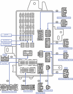


c584217.gif

Ad

Add Your Answer

×

Uploading: 0%

my-video-file.mp4

Complete. Click "Add" to insert your video. Add

×

Loading...
Loading...

Related Questions:

0helpful
1answer

2 WIRES FOR 12V SUPPLY. PIN NOs 2 WIRES for Signal PIN Nos. ??

How PC Fans Work - PCB Heaven

pcbheaven.com/wikipages/How_PC_Fans_Work/
Mar 29, 2010 - The connector of a 2-wire fan has a red and a black cable. ... The firsttwo wires are the power supply of the fan. ... This fan is designed to be controlled with a PWM signal and .... I have a four-wire (red black yellow blue) 12v fan out of an old .... My case has a number of 2 pin outputs for multiple case fans, ...

Motherboard Power Connectors ' PC Repair and ... - InformIT

www.informit.com > Articles > Hardware

InformITFeb 28, 2003 - Table 3.3 ATX Main Power Supply Connector Pinout (Wire Side View) .... The auxiliary connector has no +12v leads at all, so that is no help. Pulling up to ...Pin. Signal. Color. Yellow. +12V. 3. 1. Gnd. Black. Yellow. +12V. 4. 2.

ATX 24 pin power supply connector pinout diagram ...

pinouts.ru/Power/atx_v2_pinout.shtml

Rating: 52/60 - ‎60 votes
Jan 28, 2014 - Pinout of ATX (ATX12V) 24 pin power supply connector and layout of ... and later (ATX12V 2) is common ATX standard, 24 pin connector. ... Power Ok is a status signal generated by the power supply to notify ... 10, 12V, Yellow, +12 VDC ... 18 AWG is recommended for all wires except pin 11, which should ...

ATX power supply connector pinout diagram @ pino


1helpful
1answer

Anyone know what the switch located under the kitchen cupboard located above the sink of a 1999 Citation camper is used for?

Hi Steve:
Some of my older campers had a separate 110 light available.

Have you tried the switch when the unit is plugged into outside power as well as when it's only on battery?
0helpful
1answer

2005 toyota avalon overheated and now it will not start

Is it turning over or is it locked up - check to see if your can turn it over by hand- serious overheating can ruin an engine permanently. It can melt critical wiring as well. For many of the 90's and 2000's Toyota various models - Camry, Tacoma, 4 Runners, Corolla, and some other models it is usually caused by temperature sensitive fan switch on the radiator not operating. Electric fan on the radiator should operate when temp above 200 degrees. Less often the control relay 90987-03003 is defective. Check if bubbling in the radiator smells like exhaust. That would indicate a blown head gasket. A jumper wire from your marker light positive to the lower contact in the fan control relay socket will operate your fan when parking lights are on. The larger vehicles with more powerful radiator fans will need a hefty jumper from a headlight positive to avoid overheating the lighting wiring. Make sure the engine is off and warmed up to check the radiator core with your hand to see if it is getting circulation. If it is all cold the thermostat might be stuck.
0helpful
2answers

How do i test the fan if i already replaced the relay and the fan switch and it still doesn't work? What else could be the problem?

you could apply 12v battery power directly to the fan itself...there should be 2 wires coming from the center of the fan, follow these and you should come to a plug that you can un hook as if to remove the fan. on the fan side of the wires, hook them to 12v power, one wire + one to - if the fan does not turn, switch the wires polarity and test again. ( the fan should run either way, polarity just dictates direction of rotation) if the fan spins, the problem is on the car side. if not the fan itself is suspect. test vehicle side with known good fan or test light.
1helpful
1answer

Looking for a wiring diagram for a 2006 Ford Expedition

7way- black is 12volt (power), brown, running lights, yellow is left turn signal and stop light, green is right turn signal and stop light, white is ground, blue is brakes, and orange is aux power (can be back up lights, if trailer equipped w/ them). 6way is the same, minus orange wire. I have run into some variations to the above color codes (brown, yellow and green only-sometimes these 3 are different than stated, but only mixed as that group, as to what they control- example would be green is running lights, brown and yellow are turn signal and stop lights, the others should be as stated), if you have any trouble with things not working properly, it may be due to these variations, although the above are pretty standard. If you have an ohm meter you can check as you go (check for power at black wire- should be constant 12v, turn on turn signal and check for power-it will fluctuate from approx. 12 volts to 0 volts as the signal power pulses in the wire) hit the brakes, blue wire should show power, etc. Let me know if you need more help as you go.
0helpful
1answer

03 Mini Cooper Power Steering Fan will not run

2006 mini cooper s power steering fan seezed. replaced with new fan won't run?
0helpful
1answer

Need diagram for 2007 escape audiophile

if it is the wiring diagram for the Escape you need, here it is:

12 VOLT CONSTANT Connect to BATTERY ONLY STARTER TAN/LIGHT BLUE (+) IGNITION SWITCH HARNESS STARTER 2 N/A IGNITION 1 LIGHT GREEN/PURPLE (+) IGNITION SWITCH HARNESS IGNITION 2 N/A IGNITION 3 N/A ACCESSORY/HEATER BLOWER 1 BLACK/LIGHT GREEN (+) IGNITION SWITCH HARNESS ACCESSORY/HEATER BLOWER 2 N/A KEYSENSE N/A PARKING LIGHTS ( - ) WHITE/BLACK (-) @ SJB, Connector E, Pin 4, See NOTE *1 PARKING LIGHTS ( + ) BROWN (+) @ SJB, Connector C, Pin 19, See NOTE *1 POWER LOCK PINK/WHITE (1-Wire System) See NOTE *2 @ SJB, Connector D, Pin 22, See NOTE *1 POWER UNLOCK Same wire, See NOTE *2 See DIAGRAMS DOOR TRIGGER PINK (-) @ SJB, Connector C, Pin 28, See NOTE *1 DOMELIGHT SUPERVISION USE DOOR TRIGGER TRUNK RELEASE N/A SLIDING POWER DOOR N/A HORN YELLOW/LIGHT GREEN (-) @ SJB, Connector A, Pin 14, See NOTE *1 TACH NOT RED or WHITE/RED @ IGNITION COIL or FUEL INJECTOR WAIT TO START LIGHT N/A BRAKE LIGHT GREEN (+) @ SWITCH ABOVE BRAKE PEDAL FACTORY ALARM DISARM DARK BLUE/LIGHT GREEN (-) @ SJB, Connector D, Pin 3, See NOTE *1 ANTI-THEFT FORD'S SECURILOCK ANTI-THEFT TRANSPONDER SYSTEM TRANSPONDER @ IGNITION SWITCH TUMBLER EXTRA INFORMATION NOTE *1 The SJB (Smart Junction Block) is the FUSE/RELAY BOX on the PASSENGER SIDE of the CENTER CONSOLE. NOTE *2 This vehicle uses a 1-Wire Door Locking System, LOCK requires a (-)Negative thru a 1000 Ohm Resistor and UNLOCK requires a straight (-)Negative
0helpful
1answer

Ignition switch damaged

You will need test light/probe to check what wire does what.First one wire will have permanant 12v,that is your base wire.Use that wire to test the others.the next wire to find is accesory wire,turn radio on and join to the 12v wire each wire until radio works.if when checking the starter tries to turn that is the starter wire.The 4th wire to test is ignition wire(power to coil)plug test light/probe into positive coil wire in the engine bay and it will light up when you join the right wire to your 12v power.That leaves 2 wires wich are usualy headlights dash etc.If you tag/label as you find each wires function it makes it easier to join to after maket key.To get vehicle to run join 12v to ignition/coil wire and touch starter wire to 12v until running then remove.When stopped do not leave 12v and coil/ignition wire joined as it will eventualy destroy ignition/coil.Good luck and hope it helps
Not finding what you are looking for?

280 views

Ask a Question

Usually answered in minutes!

Top Cars & Trucks Experts

ZJ Limited
ZJ Limited

Level 3 Expert

17989 Answers

john h

Level 3 Expert

29494 Answers

Arnie Burke
Arnie Burke

Level 3 Expert

7339 Answers

Are you a Car and Truck Expert? Answer questions, earn points and help others

Answer questions

Manuals & User Guides

Loading...