2006 Volvo V50 T5 Logo
A
Anonymous Posted on Jun 11, 2012

VOLVO V50 OIL ON CAMSHAFT COVER

I have oil next to the coil packs to the rear of the camshaft cover (in every recess). Oil is seeping out of camshaft plastic cover and down back of engine. Engine has done 62k and last oil change 2k miles ago. Any idea, crankshaft breather pipe, exhaust/inlet solenoids sealing rings gone, oil filler cap tube??

1 Answer

Anonymous

Level 1:

An expert who has achieved level 1.

New Friend:

An expert that has 1 follower.

  • Contributor 1 Answer
  • Posted on Jun 11, 2012
Anonymous
Contributor
Level 1:

An expert who has achieved level 1.

New Friend:

An expert that has 1 follower.

Joined: Jun 11, 2012
Answers
1
Questions
1
Helped
381
Points
3

I will try and simplify the problem. I have an oil leak, which I traced up the back of the engine to the cylinder head area.
When I removed the top plastic cover on top of the coil packs I found oil in every recess next to the coil packs. The crankcase breather pipe was also off. The source of the leak is not evident, but it is definetely above the cylinder head gasket area.

5 Related Answers

SALMAN NASEER

  • 1011 Answers
  • Posted on Aug 18, 2008

SOURCE: high presser in tappit cover volvo 84 gl

dear,
check this manual and cure your problem

www.volvo.com/NR/rdonlyres/CC9C2F5C-B388-4F91-B9FE-BB11809AC1C3/0/PV77620154722_lores.pdf
ask more if required without hesitation dear.
regards,

Ad

Anonymous

  • 128 Answers
  • Posted on Nov 24, 2008

SOURCE: 1999 cross country v70 awd crankshaft seal replacement

Your info is confusing. The rear cam seal is not inside the timing belt cover, and the crank seal is at the bottom of the engine, while the cam seal is at the top.

Is there oil at the top, around the cam seal? Or just at the bottom? It's common for the oil pump seal to leak. If you get the oil pump reseal kit, it contains the oil pump seal and gasket, as well as the crankshaft seal. Make sure you seal the oil pump bolts, Volvo has special copper washers for this purpose.

Just try to locate the oil leak before replacing any more parts. Sometimes it can be something simple like the oil cap seal or the oil trap housing.


Bret
RepairPal.com

Anonymous

  • 16 Answers
  • Posted on Jan 17, 2009

SOURCE: I changed oil in my

Maybe you got it too tight? It doesn't need to be super tight. either that or you just didn't get the seal positioned correctly.

emissionwiz

Marvin

  • 85242 Answers
  • Posted on Jan 26, 2009

SOURCE: oil leaks

much more likely that the VC gasket's are the problem

Knight 007

Murtaza Akberali Versi

  • 767 Answers
  • Posted on Oct 27, 2009

SOURCE: oil coming out of engine oil filler cap even

The engine breather pipe seems to be blocked.
It may also damage the oil seals.

Ad

Add Your Answer

×

Uploading: 0%

my-video-file.mp4

Complete. Click "Add" to insert your video. Add

×

Loading...
Loading...

Related Questions:

0helpful
1answer

2014 dodge journey sxt 3.6 timing chain diagram

/* override srp image link color and background color */ .galleryImage { background-color: #002F56; color: rgb(0, 47, 86); } Fig. 1 Front cover pry pointsFig. 2 No. 1 piston TDC positionFig. 3 No. 1 piston TDC alignmentFig. 4 Camshaft TDC alignmentFig. 5 Timing chain alignmentFig. 6 Lefthand cam phaser alignmentFig. 7 Timing chain alignment marksFig. 8 Upper intake manifold tightening sequenceFig. 9 Valve cover tightening sequence. LefthandFig. 10 Valve cover tightening sequence. Righthand Print Options Print Text Only Print Text and images Print Timing Chain, Replace Caution: The magnetic timing wheels must not come in contact with magnets or any other strong magnetic field. This will destroy the timing wheels ability to correctly relay camshaft position to camshaft position sensor. 1. Disconnect battery ground cable. 2. Remove air cleaner housing assembly. 3. Remove upper intake manifold. 4. Remove valve covers. 5. Remove spark plugs, then raise and support vehicle. 6. Drain cooling system into suitable container. 7. Remove upper and lower oil pans. 8. 
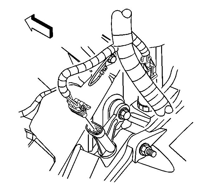
Remove righthand engine mount bracket. 9. Remove bolts from front cover. 10. Carefully remove front cover by carefully prying at seven indicated points, Fig. 1. 11. Rotate crankshaft counterclockwise to place No. 1 position at TDC on exhaust stroke by aligning dimple on crankshaft with block/bearing junction, Fig. 2. Lefthand side cam phaser arrows should point toward each other and be parallel to valve cover sealing surface. 12. Mark rotation direction of following timing chains for reference during installation: a. Lefthand side cam chain. b. Righthand side cam chain. c. Oil pump chain. d. Primary chain. 13. Reset righthand cam chain tensioner by pushing back tensioner piston and installing tensioner pin tool No. 8514, or equivalent. 14. Reset lefthand cam chain tensioner by lifting pawl, pushing back piston and installing tensioner pin tool No. 8514, or equivalent. 15. Disengage oil pump chain tensioner spring from dowel pin, then remove oil pump chain tensioner. 16. Remove oil pump sprocket T45 retaining bolt, then remove oil pump sprocket and oil pump chain. 17. Install righthand camshaft phaser lock tool No. 10202, or equivalent. Minor rotation may be required to install camshaft phaser lock. 18. Loosen both intake oil control valves, then exhaust oil control valve. 19. Remove righthand camshaft phaser lock tool, then oil control valve from righthand side intake cam phaser. 20. Pull righthand side intake cam phaser off of camshaft, then remove righthand side cam chain. 21. Remove oil control valve, then pull righthand side exhaust cam phaser off camshaft. 22. Install lefthand camshaft phaser lock tool No. 10202, or equivalent. Minor rotation may be required to install camshaft phaser lock. 23. Loosen both intake oil control valve and exhaust oil control valve. 24. Remove lefthand camshaft phaser lock tool, then oil control valve from lefthand side exhaust cam phaser. 25. Pull lefthand side exhaust cam phaser off of camshaft, then remove lefthand side cam chain. 26. Remove oil control valve, then pull lefthand side intake cam phaser off of camshaft. 27. Reset primary chain tensioner by pushing back tensioner piston and installing tensioner pin tool No. 8514, or equivalent. Remove two T30 bolts, then primary chain tensioner. 28. Remove timing chain. 29. Reverse procedure to install, note following: a. Verify No. 1 piston is positioned at TDC by aligning dimple on crankshaft with block/bearing cap junction, Fig. 3. b. Verify camshafts are set at TDC by positioning alignment holes vertically, Fig. 4. c. Ensure timing chain plated link is located at 12 o'clock when dimple on crankshaft is aligned with block/bearing cap junction, Fig. 5. d. Position lefthand side cam phasers so that arrows point toward each other and are parallel to valve cover sealing surface, Fig. 6. e. Torque idler sprocket bolt to 18 ft. lbs. f. Torque oil control valve to 110 ft. lbs. g. Torque oil pump sprocket bolt to 18 ft. lbs. h. Ensure there are 12 chain pins between exhaust cam phaser triangle marking and intake cam phaser circle marking, Fig. 7. i. Torque upper intake manifold bolts to 80 inch lbs., in sequence, as illustrated in Fig. 8. j. Torque lefthand valve cover bolts in sequence, as illustrated in Fig. 9, to 106 inch lbs. k. Torque righthand valve cover bolts in sequence, as illustrated in Fig. 10, to 106 inch lbs. l. Torque timing chain tensioner to 106 inch lbs. m. Torque timing chain guide to 106 inch lbs.
Print - As Shown Print - Fit To Page / 1
  • Fig. 1 Front cover pry points
  • Fig. 2 No. 1 piston TDC position
  • Fig. 3 No. 1 piston TDC alignment
  • Fig. 4 Camshaft TDC alignment
  • Fig. 5 Timing chain alignment
  • Fig. 6 Lefthand cam phaser alignment
  • Fig. 7 Timing chain alignment marks
  • Fig. 8 Upper intake manifold tightening sequence
  • Fig. 9 Valve cover tightening sequence. Lefthand
  • Fig. 10 Valve cover tightening sequence. Righthand
0helpful
1answer

2004 Volvo S80 2.9 non turbo has positive crankcase pressure. The driver side plastic camshaft cover popped out. Replaced cover and removed PCV box and connecting hoses,they were clean with no crude.

Your pvc or so called oil trapp is plugged replace that and look at the engine where it goes in for blockage too that's the problem Regards Chris
0helpful
1answer

Where are the camshaft and crankshaft position sensors on 2001 silverado 8.1 V8

pic-1681384701591865649-tmb.jpegCrank shaft sensor
Remove the driver side rear ignition coil bolts. Reposition the coil. Disconnect the crankshaft position (CKP) sensor electrical connector. # Use penetrating oil and allow the oil to soak around the CKP sensor prior to removing the sensor. You're looking at left, rear side of engine.
CAMSHAFT POS.
front side of engine on the drives side about half way up the timing cover, not hard to get to.
4helpful
2answers

Volvo v50 t5 oil leak

Most likely it is the breather tube and/or the oil trap box (integrated into the oil filter housing). if the box is plugged or the diaphragm is torn the box will send oil to the top of the engine via the hose.

do you also have a high pitched whistling noise?

Volvo has extended the warranty for the oil trap box (filter housing) to 120k miles and/or 10 years.
1helpful
1answer

Oil leaking from toyota camry 1992, 1994 model

You don't say what engine it has. The 4-cyl was a better than the V6 for oil leaks.

The V6 had oil leaks from

-rear bank cam cover gasket

-distributor o-ring seal

-oil filter bracket o-ring seal

-crankshaft nose oil seal (less common)

-rear main bearing oil seal (expensive, just leave it)

The 4 cyl leaked oil from

-distributor o-ring seal

-camshaft cover gasket

-rear main bearing seal (expensive, leave it)
0helpful
1answer

How do you remove the valve covers on a 2000 chevy cavalier with a 2.4

first you need to understand that your engine does not have valve covers. if you remove the ignation coil pack cover you will see to very thin covers this are not valve covers they are camshaft covers and if you unbolt them you will be removing the camshaft towers and this is not a good thing, do not unbolt them unless you are planing on replacing the timming chain because you will need to remove it to remove this covers, if you have an oil leak at the top of the engine it is most likely not the canshaft towers but is the oil sinding unit it is located under the coil cover at the back of the cylinder head....good luck
2helpful
1answer

What is the torque spec for the cam bearings on a 1998 dodge stratus with a 2.4 L?

Hi, the spec is 105 in. lbs. I have pasted the entire procedure below from autozone.com.
Thanks for using FixYa.


To install:
  1. Thoroughly clean the camshafts and related parts.
  2. The hydraulic valve lash adjusters are inside the roller camshaft followers. Make sure they are clean, well lubricated with clean engine oil and properly positioned. Install the camshaft followers in their original positions on the hydraulic adjuster and valve stem.
WARNING Make sure NONE of the pistons are at Top Dead Center (TDC) when installing the camshafts.
  1. Lubricate the camshaft bearing journals and camshaft followers with clean engine oil and install the camshafts. Install the right and left camshaft bearing caps No. 2 through No. 5 and right side No. 6. Tighten the M6 fasteners to 105 inch lbs. (12 Nm) in the correct sequence.


jturcotte_759.gif

Fig. Fig. 3: Camshaft bearing cap tightening sequence-DOHC engines


jturcotte_760.gif

Fig. Fig. 4: Camshaft bearing cap sealant application-DOHC engines

  1. Apply Mopar® Gasket Maker or equivalent sealer to the No. 1 and left side No. 6 bearing caps. Install the bearing caps and tighten the M8 fasteners to 250 inch lbs. (28 Nm). The end caps must be installed before the seals can be installed.
  2. Install the camshaft end seals.
  3. Reinstall the camshaft sprockets, if removed. Install the timing belt, taking care to make sure all timing marks are properly aligned, using the recommended procedure. Use care. DO NOT allow oil or solvents to contact the timing belt, as they can deteriorate the rubber and cause tooth skipping.
WARNING Verify that all timing marks are correct. If the timing belt or sprockets are incorrectly installed, engine damage will occur. Take time to make sure all timing marks are correctly aligned.
  1. Install the timing belt covers.
  2. Clean all valve cover sealing surfaces. Make certain the rails are flat.
  3. Install a new valve cover gasket. Apply Mopar Silicone Rubber Adhesive Sealant, or equivalent, at the camshaft cap corners and at the top edge of the 1 / 2 round seal.
Inspect the spark plug well seals for cracking and/or swelling, and replace if necessary.
  1. Install the valve cover assembly to the cylinder head and tighten the fasteners in sequence, using the following 3 steps:
    1. First: tighten all valve cover fasteners to 40 inch lbs. (4.5 Nm).
    2. Second: tighten all fasteners to 80 inch lbs. (9 Nm).
    3. Third: tighten all fasteners to 105 inch lbs. (12 Nm).

  2. Install the ignition coil pack and connect the spark plug wiring to the correct spark plugs. Tighten the coil pack retaining fasteners to 105 inch lbs. (12 Nm).
  3. Reconnect the engine ground strap.
  4. Check to be sure all vacuum lines and remaining wiring have been reconnected.
  5. An oil and filter change is recommended.
  6. Reconnect the negative battery cable and test run vehicle. Check for leaks and for proper operation.
2helpful
1answer

How to set the timing on 1998 GMC Sierra 5.7

5.0L and 5.7L Engines To Remove:
  1. Remove the crankshaft balancer.
  2. Drain the cooling system.
  3. Remove the water pump.
  4. Drain the engine oil.
  5. Remove all engine oil pan fasteners except two nuts at rear of engine.
  6. Separate the engine oil pan from the front cover.
  7. Disconnect the crankshaft position (CKP) sensor wire. gm-03-50-845.gif

  8. Remove engine front cover. gm-03-50-849.gif

  9. Pry the oil seal from the front cover.
  10. Inspect the front cover seal area and crankshaft balancer seal area for damage. gm-03-50-846.gif

  11. Rotate the crankshaft until the timing marks on the crankshaft and the camshaft sprockets are aligned.
  12. Remove the crankshaft position sensor reluctor ring. gm-03-50-847.gif

    NOTE: Free play on the slack side of the camshaft timing chain must measure less than 0.43 inch (11Mm) or timing chain and sprockets must be replaced.
  13. Remove the camshaft sprocket bolts.
  14. Remove the camshaft sprocket.
  15. Remove the camshaft timing chain. NOTE: Do not turn the crankshaft assembly after the timing chain has been removed in order to prevent damage to the piston assemblies or the valves.
    gm-03-50-848.gif

  16. Remove the crankshaft sprocket using J 5825-A.
  17. Remove the crankshaft balancer woodruff keys (if required).
To Install:
gm-03-50-850.gif

  1. Install the crankshaft balancer woodruff keys into the crankshaft.
  2. Align the crankshaft sprocket keyway with the crankshaft balancer woodruff key. WARNING
    Wear eye protection when installing crankshaft sprocket.
    gm-03-50-851.gif

  3. Use J 5590 to install crankshaft sprocket.
  4. Install the camshaft sprocket and camshaft timing chain. 9308kg61.gif

  5. Ensure that the crankshaft sprocket alignment mark is in the 12 o'clock position and the camshaft sprocket alignment mark is at the 6 o'clock position.
  6. Install the camshaft sprocket bolts and tighten the camshaft sprocket bolts;
    • Torque to: 18 ft. lbs. (25 Nm)
  7. Install the crankshaft position sensor reluctor ring until completely seated against crankshaft sprocket. NOTE: The composite type engine front cover and seal must not be reused. Always install a new engine cover with a new seal.
  8. Install new engine front cover and bolts.
    • Torque bolts to: 106 in. lbs. (12 Nm)
  9. Clean sealer from corners of oil pan gasket where it meets the engine front cover. gm-03-50-775.gif

  10. Apply a 0.196 in (5 mm) bead of adhesive, GM P/N 12346141 or equivalent, 1.0 in (25 mm) long to the engine front cover to engine block junction.
  11. Install oil pan bolts.
    • Torque bolts to: 106 in. lbs. (12 Nm)
  12. Tighten oil pan nuts.
    • Torque bolts to: 18 ft. lbs. (25 Nm)
  13. Connect the crankshaft position sensor wire.
  14. Install the water pump.
  15. Install the crankshaft balancer.
  16. Fill the engine to the proper level with oil.
  17. Fill the engine to the proper level with coolant.
  18. Test drive the vehicle to confirm the repairs.
0helpful
1answer

How do you time a 350 gmc motor

4.8L, 5.3L and 6.0L Engines
    • Timing mark alignment-4.8L, 5.3L & 6.0L 9308kg61.gif

    • Locate the camshaft sprocket alignment mark in the 6 o'clock position and install the camshaft sprocket and timing chain
    • Camshaft sprocket bolts and tighten the camshaft sprocket bolts;
      1. Torque to: 26 ft. lbs. (35 Nm)
    • Oil pump
    NOTE: Do not lubricate the oil seal sealing surface.
  1. Lubricate the outer edge of the oil seal with clean engine oil.
  2. Lubricate the front cover oil seal bore with clean engine oil.
  3. Install the crankshaft front oil seal with a suitable seal installer. NOTE: Do not apply any type sealant to the front cover gasket (unless specified). Special tools are used to properly align the engine front cover at the oil pan surface and to center the crankshaft front oil seal.
  4. Install the front cover gasket, cover, and bolts onto the engine.
  5. Install the front cover-to-oil pan bolts and do not overtighten.
  6. Tighten the cover bolts finger tight and do not overtighten. J41480 installation-4.8L, 5.3L & 6.0L 9308kg59.gif

  7. Start the J41480 or other suitable tool to front cover bolts but don’t tighten the bolts yet. NOTE: Align the tapered legs of the tool with the machined alignment surfaces on the front cover.
    Seal alignment tool installation-4.8L, 5.3L & 6.0L 9308kg84.gif

  8. Install tool J41476 or other suitable tool.
  9. Install the crankshaft balancer bolt and tighten the crankshaft balancer bolt by hand until snug but do not overtighten.
  10. Tighten the J41480 bolts and front cover bolts;
    • Torque to: 18 ft. lbs. (25 Nm).
  11. Remove the tools. NOTE: Place a straight edge across the engine block and front cover oil pan sealing surfaces. Avoid contact with the portion of the gasket that protrudes into the oil pan surface. Insert a feeler gauge between the front cover and the straight edge tool. The cover must be flush with the oil pan surface or no more than 0.5 mm (0.02 in) below flush. If the front cover-to-engine block oil pan surface alignment is not within specifications, repeat the cover alignment procedure. If the correct front cover-to-engine block alignment cannot be obtained, replace the front cover.
  12. Snug the oil pan-to-cover bolts in order to position the cover at the pan rail.
  13. Tighten the oil pan-to-front cover bolts;
    • Torque to: 18 ft. lbs. (25 Nm).
  14. Tighten the front cover bolts;
    • Torque to: 18 ft. lbs. (25 Nm).
  15. Install the crankshaft balancer and bolt (See: Crankshaft Damper).
  16. Install the water pump (See: Water Pump).
  17. Fill the engine to the proper level with oil.
  18. Fill the engine to the proper level with coolant.
  19. Test drive the vehicle to confirm the repairs.
6.6L Engine To Remove:
NOTE: The 6.6L engine uses gears in place of a timing chain. For removal and installation, please see the Camshaft and Lifters procedure. This procedure covers the removal of the front cover and seal.
  1. Before servicing the vehicle refer to the precautions at the beginning of this section.
  2. Remove the upper intake manifold sight shield as follows:
    • Remove the retaining bolt in the front of the shield
    • Lift up on the front of the shield, then lift the shield off the rear bracket
  3. Drain the cooling system.
  4. Remove or disconnect the following:
    • Negative battery cables
    • Right front wheel
    • Right front fender splash shield
    • Upper fan shroud
    • Fan clutch (See: Engine Fan and Clutch)
    • Drive belt
    • Oil dipstick tube
    • Thermostat housing crossover
    • Crankshaft damper (See: Crankshaft Damper)
    • Crankshaft front oil seal
    • Water pump (See: Water Pump)
    • Camshaft sensor electrical connector
    • Camshaft sensor bolt and sensor
    • Crankshaft Position (CKP) sensor connector, bolt and sensor
    • CKP sensor spacer bolts and spacer
    • 5 bolts securing the upper oil pan to the front cover
    • Bracket bolts and the bracket for the turbocharger outlet coolant pipe
    • Engine front cover bolts
    • Use a suitable seal cutter to separate the front cover from the cylinder block and upper oil pan NOTE: Do not bend the turbocharger outlet pipe.
    • O-ring from the front cover Engine front cover-6.6L engine 9348ng32.gif

    • Oil pressure relief valve from the front cover
To Install:
  1. Clean and inspect all sealing surfaces.
  2. Install or connect the following:
    • Oil pressure relief valve with a new O-ring and tighten the valve
      1. Torque to: 30 ft. lbs. (41 Nm)
  3. Apply a 1/8 in. (2-3mm) wide to 1/16 in. (0.5-1.5mm) high bead of sealant to the front cover sealing surfaces to the engine block and oil pan.
  4. Install or connect the following:
    • New front cover O-ring after lubricating it with engine oil
    • Front cover and bolts and tighten the front cover bolts
      1. Torque to: 15 ft. lbs. (20 Nm)
    • Upper oil pan-to-front cover bolts and tighten the bolts
      1. Torque to: 15 ft. lbs. (20 Nm)
    • Turbocharger coolant outlet pipe bracket and bolts and tighten the bolts
      1. Torque to: 15 ft. lbs. (20 Nm).
    • Camshaft sensor and bolt and tighten the bolt
      1. Torque to: 80 inch lbs. (9 Nm)
    • Camshaft sensor connector NOTE: The CKP sensor spacers are machined with different timing positions. If you have to replace a spacer, make sure it has the same part number.
    • CKP sensor spacer and spacer bolts and tighten the bolts
      1. Torque to: 89 inch lbs. (10 Nm)
    • CKP sensor and bolt and tighten the bolt
      1. Torque to: 89 inch lbs. (10 Nm)
    • Water pump (See: Water Pump)
    • Crankshaft front oil seal
    • Crankshaft damper (See: Crankshaft Damper)
    • Thermostat housing crossover
    • Oil fill tube
    • Drive belt
    • Upper fan shroud
    • Right front fender splash shield and wheel
    • Negative battery cables
  5. Refill the cooling system with the proper type and quantity of antifreeze.
  6. Inspect the engine for leaks.
  7. Test drive the vehicle to confirm the repairs.
0helpful
1answer

1999 cross country v70 awd crankshaft seal replacement

Your info is confusing. The rear cam seal is not inside the timing belt cover, and the crank seal is at the bottom of the engine, while the cam seal is at the top.

Is there oil at the top, around the cam seal? Or just at the bottom? It's common for the oil pump seal to leak. If you get the oil pump reseal kit, it contains the oil pump seal and gasket, as well as the crankshaft seal. Make sure you seal the oil pump bolts, Volvo has special copper washers for this purpose.

Just try to locate the oil leak before replacing any more parts. Sometimes it can be something simple like the oil cap seal or the oil trap housing.


Bret
RepairPal.com
Not finding what you are looking for?

391 views

Ask a Question

Usually answered in minutes!

Top Volvo Experts

ZJ Limited
ZJ Limited

Level 3 Expert

17989 Answers

Ronny Bennett Sr.
Ronny Bennett Sr.

Level 3 Expert

6988 Answers

Thomas Perkins
Thomas Perkins

Level 3 Expert

15088 Answers

Are you a Volvo Expert? Answer questions, earn points and help others

Answer questions

Manuals & User Guides

Loading...