EliteGroup P4VMM2 Motherboard Logo

Related Topics:

Posted on Sep 08, 2009
Answered by a Fixya Expert

Trustworthy Expert Solutions

At Fixya.com, our trusted experts are meticulously vetted and possess extensive experience in their respective fields. Backed by a community of knowledgeable professionals, our platform ensures that the solutions provided are thoroughly researched and validated.

View Our Top Experts

I need connection diagram 4 my P4vmmr motherboard

1 Answer

Anonymous

Level 3:

An expert who has achieved level 3 by getting 1000 points

All-Star:

An expert that got 10 achievements.

MVP:

An expert that got 5 achievements.

President:

An expert whose answer got voted for 500 times.

  • Master 1,015 Answers
  • Posted on Sep 08, 2009
Anonymous
Master
Level 3:

An expert who has achieved level 3 by getting 1000 points

All-Star:

An expert that got 10 achievements.

MVP:

An expert that got 5 achievements.

President:

An expert whose answer got voted for 500 times.

Joined: Sep 04, 2009
Answers
1015
Questions
0
Helped
451841
Points
3407

Here is the link to the esc website where you can find the PDF manual that will have the diagram for your board....You also will need the version number of the board.

http://www.ecsusa.com/ECSWebSite/Products/ProductList_new.aspx?CategoryID=1&MenuID=7&LanID=9

Add Your Answer

×

Uploading: 0%

my-video-file.mp4

Complete. Click "Add" to insert your video. Add

×

Loading...
Loading...

Related Questions:

0helpful
1answer

Need connection diagram for awrdacpi motherboard need front panel connection diagram for awrdacpi motherboard...I need front panel connection diagram for awrdacpi motherboard

http://support.asus.com/download.aspx?SLanguage=en&p=1&m=M2N-MX+SE&hashedid=LqXTJVvWNyI6cj2d

Download the installation manual in your language from there.
0helpful
1answer

It is same for my P5KPL AM/PS front pannel is not working for this mainboard. My OS is windowdow xp 7

For that you need to check the front panel connection to motherboard. You can see diagram below . Click here Download manual from below link then connect front panel connection to motherboard. You can also find the diagram on motherboard there are some pins on corner of the motherboard where you need to terminate front panel connection. You can read diagram near those pins. Let me know if you need further assistance. Thanks for using FixYa.
0helpful
1answer

Motherboard diagram

A Computer Motherboard Diagram motherboard-diagram-01.jpg 
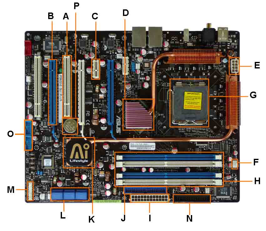
Once you know what you are looking at, you can recognize the components on any motherboard layout. A computer motherboard diagram is very useful for when you need to replace motherboard, do motherboard upgrades, troubleshoot motherboard, or build your own computer.
  1. PCI Slot - This board has 2 PCI slots. These can be used for components such as Ethernet cards, sound cards, and modems.
  2. PCI-E 16x Slot - There are 2 of them on this motherboard diagram, both are blue. These are used for your graphics card. With two of them onboard, you can run 2 graphics cards in SLI. You would only need this if you are a gamer, or working with high end video / graphics editing. These are the 16x speed versions, which are currently the fastest.
  3. PCI-E 1x Slot - Single slot - In the PCIe 1.x generation, each lane (1x) carries 250 MB/s compared to 133 MB/s for the PCI slots. These can be used for expansion cards such as Sound Cards, or Ethernet Cards.
  4. Northbridge - This is the Northbridge for this motherboard. This allows communication between the CPU and the system memory and PCI-E slots.
  5. ATX 12V 2X and 4 Pin Power Connection Power Connection - This is one of two power connections that supply power to the motherboard. This connection will come from your Power Supply.
  6. CPU-Fan Connection - This is where your CPU fan will connect. Using this connection over one from your power supply will allow the motherboard to control the speed of your fan, based on the CPU temperature.
  7. Socket - This is where your CPU will plug in. The orange bracket that is surrounding it is used for high end heat sinks. It helps to support the weight of the heat sink.
  8. Memory Slots - These are the slots for your RAM. Most boards will have 4 slots, but some will only have 2. The color coding you see on the motherboard diagram is used to match up RAM for Dual-Channel. Using them this way will give your memory a speed boost.
  9. ATX Power Connector - This is the second of two power connections. This is the main power connection for the motherboard, and comes from the Power Supply.
  10. IDE Connection - The IDE (Integrated Drive Electronics) is the connection for your hard drive or CD / DVD drive. Most drives today come with SATA connections, so you may not use this.
  11. Southbridge - This is the controller for components such as the PCI slots, onboard audio, and USB connections.
  12. SATA Connections - These are 4 of the 6 SATA connections on the motherboard. These will be used for hard drives, and CD / DVD drives.
  13. Front Panel Connections - this is where you will hook in the connections from your case. These are mostly the different lights on your case, such as power on, hard drive activity etc.
  14. FDD Connection - The FDD is the Floppy Disk controller. If you have a floppy disk drive in your computer, this is where you will hook it up.
  15. External USB Connections - This is where you will plug in external USB connections for your case or USB bracket.
  16. CMOS battery - This is the motherboard's battery. This is used to allow the CMOS to keep its settings.

3helpful
1answer

Need connection diagram for awrdacpi motherboard

I need front panel connection diagram for awrdacpi motherboard
0helpful
1answer

Changing my case

If you want to download the Manual for your Motherboard, I've included the link below. Otherwise I will provide a rough diagram of the Panel header for connecting your case to the Motherboard.
http://www.ecs.com.tw/ECSWebSite/Downloads/ProductsDetail_Download.aspx?detailid=422&DetailName=New&DetailDesc=&CategoryID=1&MenuID=6&LanID=0


[2][4][6][8][10]
[1][3][5][7][ 9 ]

HDD Led
+ = 1
- = 3
Power/ PWR LED
+ = 2
- = 4
Power switch
Pins 6 & 8

Reset
Pins 5 & 7

RSVD (Reserved)
pin 9

NC (No Connection)
Pin 10

Hope this helps you
Dave
2helpful
1answer

Wiring

The user guide for the motherboard should have a full diagram for all the wiring you have. Here is the link: http://www.manualnguide.com/dl/8959/
0helpful
1answer

Intel PENTIUM-4 865GV CHIP Circuit diagram

There has been no need for a Turbo LED for at least 8 years and probably closer to 10 years. Turbo LEDs were primarily used with the old 386 and 486 computers dating back to 92-96 and even a bit earlier then that.
865GV is a chipset number, not a motherboard model #. Many different companies produced motherboards based on the 865GV chipset and that information alone is BY FAR NOT ENOUGH information for us to work with in determining exactly which motherboard you are dealing with.
There should be a motherboard model # printed on the motherboard somewhere, might be hard to see, but if you can't find one, the chances are you are using one of the cheapest low-end motherboards made and the stituation will only get worse from there.
13helpful
7answers

Need to connect Mercury PVM900M motherboard cables

my name is Allan kaitila from Tanzania
I bought a motherboard Mercury PVM900M,but i dont know how to conect it.

So may I have its Diagram that shows
The following wires and send it to me through [email protected]

1. SYS_FAN
2. CPU_FAN
3. ATX_12V1
4. POWER SW
5. RESET SW
6. H.D.D LED
7. POWER LED
8 MIC
9. L-RET
10. L-OUT
11. R-RET
12. R-OUT
13. G
14. USB1
15. G
16. USB2
17. G
18. SPEAKER

Not finding what you are looking for?

298 views

Ask a Question

Usually answered in minutes!

Top EliteGroup Computers & Internet Experts

Grand Canyon Tech
Grand Canyon Tech

Level 3 Expert

3867 Answers

Jose Ramirez

Level 2 Expert

264 Answers

Cindy Wells

Level 3 Expert

6688 Answers

Are you an EliteGroup Computer and Internet Expert? Answer questions, earn points and help others

Answer questions

Manuals & User Guides

Loading...