1995 Nissan 200SX Logo
Posted on Jul 16, 2009

How would I install an upper suspension arm to

How would I install a front upper suspension arm to reduce stress and what would make a grinding or knocking noise in the suspension of my nissan. Why does a Nissan Primera need to be run for some time before stopping. It seems to flood and won't start if started and stopped cold. I can't type in Nissan Primera 1993 as your categories won't give me these options.

1 Answer

Anonymous

Level 1:

An expert who has achieved level 1.

Mayor:

An expert whose answer got voted for 2 times.

Problem Solver:

An expert who has answered 5 questions.

  • Contributor 5 Answers
  • Posted on Jul 20, 2009
Anonymous
Contributor
Level 1:

An expert who has achieved level 1.

Mayor:

An expert whose answer got voted for 2 times.

Problem Solver:

An expert who has answered 5 questions.

Joined: Jul 20, 2009
Answers
5
Questions
0
Helped
2309
Points
9

Nissan primera in the US is called an Infiniti G20. the grinding or knocking if its coming from the front, is gonna be the tension rod bushings are warn out. get new tension rods for real cheap. thats all i can help with, suspension is my thing, motor is not.

Add Your Answer

×

Uploading: 0%

my-video-file.mp4

Complete. Click "Add" to insert your video. Add

×

Loading...
Loading...

Related Questions:

0helpful
1answer

Torque settings

Torque settings Working on your car means you have to torque parts up when you fit them. Using correct torque levels is very important. Bolts will be tensioned when torquing up. Always use a torque wrench when installing parts on your car!
Too much tension means the bolt will be stressed too much and can ultimately break.
Not enough tension means the bolt can either run loose or it can move around. This will damage the bolt and it's brackets. This can ultimately also lead to catastrophic failures.
Only use 8.8 grade bolts in suspension applications. (wishbones, dampers etc.) 10.9 grade or even worse 12.9 grade bolts are hardened.

The hardening process will improve the maximum possible load on the bolt, but it will also make the bolt relatively brittle.

Within suspension parts, you would rather see bolts bend than sheer. 8.8 grade bolts have the tendacy to bend, any hardended bolts have the tendacy to sheer.
Below is a guideline to the torque levels used on Metric bolts.
Bolt grades are printed on the head of the bolt.
Bolt Size 8.8 10.9 12.9 A2-70 (Stainless) 6mm (M6) 9Nm 13Nm 14Nm 7Nm 8mm (M8) 23Nm 33Nm 40Nm 17Nm 10mm (M10) 45Nm 65Nm 70Nm 33Nm 12mm (M12) 80Nm 115Nm 125Nm 57Nm 14mm (M14) 125Nm 180Nm 195Nm 16mm (M16) 195Nm 280Nm 290Nm Note than when fitting bolts into Ally threads like rivnuts, manifolds and S1 uprights then the torque may need to be reduced.

Special note for Mr. Wiki - This is the thread size, not the head size.
Engine mount torque settings (K-Series) Nm RH engine mounting bracket to engine RH engine mounting bracket to rubber mounting RH engine rubber mounting to chassis RH engine steady arm bolts LH engine mounting bracket to rubber mounting LH engine mounting bracket to engine Lower steady arm bracket to sump Lower steady arm bolts Use Permabond A130(A912E7033V) on the sump end bolt on the lower steady arm
Front suspension torque settings (S2 K-Series) Nm Upper and lower wishbone pivot bolts Upper swivel joint to steering arm Lower swivel joint to plinth Steering arm to hub carrier Track rod end to steering arm Damper to lower wishbone Damper to top anchor bracket Damper anchor bracket to chassis Hub bearing unit to hub carrier Brake caliper to hub carrier Anti-roll bar rubber bush mounting clamps Anti-roll bar drop links Rear suspension torque settings (S2 K-Series) Nm Upper and lower wishbone pivot bolts Upper and lower swivel joint ball pins Upper swivel joint plinth to hub carrier Toe-link outer ball joint to hub carrier* Toe-link inner ball joint/wishbone to sub frame** Toe link ball joint lock nuts Damper to lower wishbone Damper to chassis Upper brake caliper to hub carrier (M10) Lower brake caliper to hub carrier (M8) Hub bearing unit to hub carrier Rear hub nut ,*Check batch number of ball joint is 43273 or later
,**Check batch number of ball joint is 43725 or later
0helpful
1answer
0helpful
1answer

1991 primera how to replace upper suspension arms

It is pretty straightforward.

Raise and support the vehicle. Remove the tire and wheel assemblies. Remove the bolts from both ends of the upper suspension arm. Remove the suspension arm. Reverse procedure to install.

You may have to pry the thing with a pry bar to get the outer end of the suspension arm separated from the steering knuckle/strut lower end.
2helpful
1answer

What does the control arm on the front left driver side supposed to look like fully assembled

Hello! First diagram is the lower...Second is the upper..Guru...saailer

LOWER IDENTIFICATION:


Item
Part Number Description 1
5495 Stabilizer Bar Link Bolt and Bushing Assembly 2
18A192 Nut, Washer and Bushing Assembly 3
808264 Bolt 4
5005 Frame 5
5B326 Torsion Bar (LH) 6
5B327 Torsion Bar (RH) 7
620481 Nut 8
5C491 Nut and Washer 9
3079 Front Suspension Lower Arm (LH) 10
3078 Front Suspension Lower Arm (RH) 11
3A130 Tie Rod End 12
808166 Nut 13
808167 Nut 14
5K483 Front Stabilizer Bar Link 15
5482 Front Stabilizer Bar 16
5484 Front Stabilizer Bar Bushing 17
3B353 Front Stabilizer Retainer 18
N807396-S100 Bolt A
- Tighten to 40-55 Nm
(30-40 Lb-Ft) B
- Tighten to 150-200 Nm (111-148 Lb-Ft) C
- Tighten to 21-29 Nm
(15-21 Lb-Ft)


UPPER IDENTIFICATION:
Item Part Number Description 1 3C156 Damper Assembly (RH) 2 805348 Nut and Washer 3 - Shock Absorber Insulator
(Part of 18198) 4 3C157 Damper Assembly (LH) 5 3020 Front Suspension Bumper 6 3083 Front Suspension Upper Arm Assembly A - Tighten to 34-47 Nm
(25-35 Lb-Ft)


LOWER DIAGRAM FOLLOWED BY UPPER:
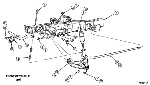
2_12_2012_9_47_51_pm.gif2_12_2012_9_54_26_pm.gif

I’m happy to help further over the phone at https://www.6ya.com/expert/david_6df67de3b14de867

3helpful
1answer

How do i change my rubber bushings on the front suspention of my 1997 dodge ram 1500

opper Control Arm Bushings
  • To access the upper control arm, remove the shock absorber and the strut bar. Also, disconnect the sway bar from the lower control arm, if your particular Ram model is equipped with it. After that, you can hold the coil spring in place with a spring compressor.
    Secure the wheel hub assembly to the chassis using a wire before you disconnect the upper ball joint. This will prevent damage to the brake hose. When ready, release the ball joint using a ball-stud loosening tool (see Resources).
    The upper control arm mounts to the chassis with a cam bolt assembly. Once removed, you can place the control arm on a vise and remove the bushings using a bushing service tool (see Resources). When installing the new bushings, do not use any lubricant but make sure the flange on the bushing end seats properly on the arm bore. Then re-install the upper control arm. When finished, take your Dodge vehicle to a good shop to align the front suspension.
Lower Control Arm Bushings
  • Remove the shock absorber and strut bar. If your particular model is equipped with a sway bar, disconnect it from the lower control arm.
    Secure the coil spring with a spring compressor and release the lower ball joint from the wheel/hub assembly using a ball stud loosening tool (see Resources).
    Now you can release the lower control arm by removing the rear mounting bolts. Remove the bushings with a bushing service tool (see Resources). When installing the new bushings, do not use lubricant and make sure they seat properly on the control arm bore. Then replace the lower control arm. When finished, take your Dodge vehicle to a good shop to align the front suspension
3helpful
2answers

HOW TO REMOVE AND REPLACE MOUNTAINEER UPPER BALL JOINTS?

Upper Ball Joint Removal & Installation Ball joints on this vehicle are an integral part of the control arm. If the ball joint is defective, the entire control arm must be replaced.
---
Upper Control Arm Removal & Installation
  1. Before servicing the vehicle, refer to the precautions in the beginning of this section.
  2. Remove or disconnect the following:
    • Wheel and tire assembly
    • Brake disc shield
  3. Use a jack to support the front suspension lower arm.
  4. Mark the position of the front suspension upper arm adjustment cams.
  5. Remove the upper ball joint retaining nut and pinch bolt.
  6. Separate the ball joint from the front wheel spindle
  7. Remove the front suspension upper control arm.
To Install:
  1. Installation is the reverse of removal. Align the marks made during removal on the front suspension upper arm adjustment cam. The forward front suspension upper arm nut must be tightened first while the arm is held at the curb position ride height.
  2. Observe the following torques:
    1. Control arm attaching nuts: 98 ft. lbs. (133Nm)
    2. Pinch bolt: 46 ft. lbs. (63Nm)
prev.gif next.gif
3helpful
1answer

How to change 2007 dodge 1500 front struts?

Removal & Installation Independent Front Suspension – 2WD Vehicles To Remove:
  1. Before servicing the vehicle, refer to the precautions at the beginning of this section.
  2. Safely raise and support the vehicle.
  3. Support the lower control arm outboard end.
  4. Remove or disconnect the following:
    • Upper shock absorber nut, retainer and grommet
    • Lower nuts and shock absorber
To Install:
  1. Install or connect the following:
    • Lower retainer and grommet on the shock absorber stud and insert shock absorber through frame bracket hole
    • Lower nuts
      1. Torque to: 25 ft. lbs. (34 Nm)
    • Upper grommet, retainer and new nut (or existing nut with Mopar Lock N Seal or Loctiti 242) on the shock absorber stud
      1. Torque to: 40 ft. lbs. (54 Nm)
  2. Remove support from lower control arm outboard end.
  3. Lower the vehicle.
Independent Front Suspension – 4WD Vehicles To Remove:
  1. Before servicing the vehicle, refer to the precautions at the beginning of this section.
  2. Safely raise and support the vehicle.
  3. Remove tire and wheel assembly.
  4. Support the lower control arm outboard end.
  5. Remove or disconnect the following: dod_ram15_02-04_4wd_shock.gif

    • Upper shock nut with insulator and retainer
    • Lower shock bolt
    • Shock absorber
To Install:
  1. Install or connect the following:
    • Upper part of shock absorber into frame bracket with insulators and retainers and nut
      1. Torque to: 40 ft. lbs. (54 Nm)
    • Lower part of shock absorber into lower control arm with the bolt
      1. Torque to: 100 ft. lbs. (135 Nm)
  2. Remove support from lower control arm.
  3. Install tire and wheel assembly.
  4. Lower the vehicle.
Link/Coil Front Suspension To Remove:
  1. Before servicing the vehicle, refer to the precautions at the beginning of this section.
  2. Remove or disconnect the following:
    • Nut, retainer, and grommet from upper stud in engine compartment dod_ram15_02-04_shock.gif

    • Nuts from upper shock bracket
  3. Lower bolt from axle bracket and shock absorber from engine compartment
To Install:
  1. Position lower retainer and grommet on upper stud and insert the shock through the spring from the engine compartment.
  2. Install or connect the following:
    • Lower bolt
      1. Torque to: 100 ft. lbs. (135 Nm)
    • Upper shock bracket and nuts
      1. Torque to: 55 ft. lbs. (75 Nm)
    • Upper grommet, retainer and upper shock absorber nut
      1. Torque to: 35 ft. lbs. (47 Nm)
prev.gif next.gif
0helpful
1answer

Replacing front struts

Okay....here is the steps first....and then the directions on how to use the tools:

  1. Raise and properly support the vehicle.
  2. Remove the front wheel.
  3. Detach the shock absorber lower mount by removing the two bolts.
  4. Remove the retainer nut, retainer, cushion and shock absorber.
  5. Detach the cushion retainer from the shock absorber.
  6. Compress the coil spring with a commercially available spring compressor.
  7. Detach the stabilizer bar.
  8. Support the upper suspension arm and steering knuckle securely.
  9. Remove the cotter pin.
  10. Loosen and remove the nut.
  11. Using a ball joint removal tool, detach the lower ball joint from the lower control arm.
  12. Loosen the suspension arm set bolt.
  13. Remove the suspension arm set bolt nut.
  14. Remove the nut from the strut bar front set bolt.
  15. Pull out both set bolts.
  16. Remove the lower suspension arm and coil spring. To install:
  17. Installation is the reverse of removal. Note the following torque specifications:
    1. Strut bar front set bolt: 221 ft. lbs. (300 Nm)
    2. Lower suspension arm set bolt: 148 ft. lbs. (200 Nm)
    3. Lower ball joint nut: 80 ft. lbs. (110 Nm)
    4. Lug nuts: 83 ft. lbs. (110 Nm).
0helpful
1answer

How to change lower ball joints

part of lower arm assembly only.

Installation
  1. Inspect lower ball joint boots and seals for damage and replace if required. Lower ball joint and seal is part of front suspension lower arm and must be replaced as an assembly.
  1. NOTE: Do not tighten the front suspension lower arm bolts and nuts to the specified torque until the end of assembly. Install nuts and tighten until snug.

    Position the front suspension lower arm in the front crossmember. Install the bolts. Install the nuts and tighten until snug.
  1. Install torsion bar. Refer to Torsion Bar in this section.
  1. Raise the front suspension lower arm to allow installation of front suspension lower arm ball joint into spindle bore.
  1. Lower front suspension lower arm with a jack while making sure lower ball joint is seated in spindle bore. Install the lower ball joint attaching nut and tighten to 113-153 Nm (82-113 lb-ft). Install a new cotter pin.
  1. Raise vehicle. Position the front shock absorber and install the nut/washer/bushing assembly. Tighten nut to 40-55 Nm (30-40 lb-ft).
  1. Install the two nuts attaching the front shock absorber to the lower control arm and tighten to 21-29 Nm (15-21 lb-ft).
  1. NOTE: Front suspension lower arms must be in the horizontal or curb position (vehicle on the ground) when tightening the front stabilizer bar link bolts. Use jackstands to raise the front suspension lower arms to the horizontal position or lower the vehicle to the ground (curb position).

    Lower the vehicle to the ground.
  1. Connect the stabilizer bar link bolt to the front suspension lower arm and tighten to 13-17 Nm (10-13 lb-ft).
  1. Tighten nuts and front suspension lower arm bolts to the No. 1 crossmember to 150-200 Nm (111-148 lb-ft).
  1. Check ride height and align as necessary. Refer to Section 04-00 .
  1. Lower the vehicle.
0helpful
1answer

What are the torque specs for 1990 dodge dakota front suspension.

call carquest or other parts house and ask them for the torque specs or a front end alignment shop.
Not finding what you are looking for?

479 views

Ask a Question

Usually answered in minutes!

Top Nissan Experts

ZJ Limited
ZJ Limited

Level 3 Expert

17989 Answers

Thomas Perkins
Thomas Perkins

Level 3 Expert

15088 Answers

Ronny Bennett Sr.
Ronny Bennett Sr.

Level 3 Expert

6988 Answers

Are you a Nissan Expert? Answer questions, earn points and help others

Answer questions

Manuals & User Guides

Loading...