Download manual from the attached link:
https://www.gmupfitter.com/publicat/2004_BB/2003_Beyond_LD_Electric_CK.pdf
http://alarmsellout.com/support/diagrams/vehicle/CHEVROLET%20SILVERADO%201988-2005.pdf
This may help:
http://www.automotivetroubleshootingsecrets.com/2003_Chevrolet_Silverado_1500_4.8L_No_Start_Stall.html
This may help:
2003-2006 Chevrolet Silverado Wiring Diagram:
Listed below is the vehicle specific wiring diagram for your car alarm, remote starter or keyless entry installation into your
2003-2006 Chevrolet Silverado . This information outlines the wires location, color and polarity to help you identify the proper connection spots in the vehicle. Please be sure to test all of your wires with a digital multimeter before making any connections.
PART
COLOR
LOCATION
12 VOLT CONSTANT
RED (+)
@ IGNITION SWITCH HARNESS
STARTER
YELLOW (+)
@ IGNITION SWITCH HARNESS
STARTER 2
N/A
IGNITION 1
PINK (+)
@ IGNITION SWITCH HARNESS
IGNITION 2
WHITE (+), SEE NOTE #2
@ IGNITION SWITCH HARNESS
IGNITION 3
N/A
ACCESSORY/HEATER BLOWER 1
ORANGE (+)
@ IGNITION SWITCH HARNESS
ACCESSORY/HEATER BLOWER 2
BROWN (+)
@ IGNITION SWITCH HARNESS
KEYSENSE
N/A
PARKING LIGHTS ( - )
GRAY/BLACK (-)
@ BCM, BROWN PLUG, PIN B2, SEE NOTE #3
PARKING LIGHTS ( + )
BROWN (+)
IN DRIVERS KICK PANEL
POWER LOCK
SEE NOTE #1, (for BASE MODEL TRUCKS, SEE NOTE #4)
POWER UNLOCK
SEE NOTE #1, (for BASE MODEL TRUCKS SEE NOTE #4)
DOOR TRIGGER
GRAY/BLACK (-)(DRIVERS) and BLACK/WHITE (-)(PASSENGER), SEE NOTE #5
@ EACH DOOR MODULE, IN EACH DOOR
DOMELIGHT SUPERVISION
GRAY/BLACK (-)
@ BCM, BLACK PLUG, PIN E, SEE NOTE #3
TRUNK RELEASE
N/A
SLIDING POWER DOOR
N/A
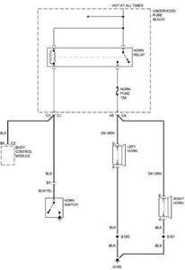
HORN
BLACK/YELLOW to BLACK (-)
@ STEERING COLUMN HARNESS
TACH
Any wire NOT, PINK, BLACK or BROWN (AC)
@ IGNITION COILS or FUEL-INJECTORS
WAIT TO START LIGHT
DK. BLUE (-)
@ INSTRUMENT CLUSTER, PIN A2
BRAKE
WHITE (+)
@ BRAKE PEDAL SWITCH
FACTORY ALARM DISARM
LT. GREEN (-)
@ DRIVERS DOOR MODULE, IN DOOR, BLACK 26-PIN PLUG PIN 15
ANTI-THEFT
GM'S PASSLOCK 2 ANTI-THEFT SYSTEM, SEE NOTE #1
@ IGNITION SWITCH
EXTRA INFORMATION
NOTE #1: This vehicle uses GM'S PASSLOCK 2 ANTI-THEFT SYSTEM that requires a 791 Bypass Module to Remote Start, if you are using a REMOTE STARTER ONLY, use the 791. IF you are installing a REMOTE STARTER with KEYLESS ENTRY you MUST USE the INTERFACE BYPASS MODULE, Part # DB-ALL or XK09, EITHER Bypass will do the Anti-theft and Keyless entry. If connecting a keyless entry only you can use the GMDL-BP. NOTE #2: The IGNITION #2 wire WHITE must be connected to prevent a CHECK ENGINE LIGHT from turning on and to prevent DAMAGE to the TRANSMISSION on this Vehicle. NOTE #3; The BCM is located under the Drivers Side of the dash, the BCM has 6 plugs on it, with the PURPLE plug on the back. NOTE #4: On BASE model truck the DOOR LOCK INTERFACE MODULE is not necessary, the LOCK wire is a LT BLUE (TYPE B) @ the BCM, LT BLUE PLUG, PIN B5, and the UNLOCK wire is a WHITE (TYPE B) @ the BCM, LT BLUE PLUG, PIN B10. NOTE #5: On BASE Model trucks, the Door Trigger wires are @ the BCM, LT BLUE PLUG, PINS B4 and A5. On 4-Door Trucks the LEFT REAR Door is a LT BLUE/BLACK (-) PIN A3 and the RIGHT REAR Door is a LT GREEN/BLACK (-) PIN A2, located in a PURPLE PLUG at the BCM, use all 4 wires and diode isolate when installing an alarm system.


×