Cars & Trucks Logo

Related Topics:

Posted on Mar 14, 2011

[email protected] installing a new fan that has only two wires.the factory harness has what apears to be a sensor that mounts in the fan shroud.the factory fan has three wire.one a white wire going thru the sensor to the fan.how do i hook this new fan up?

1 Answer

A

Anonymous

If you read your question,it is clear to me
at least, that you have the wrong motor

You said you need a white wire going
to the fan & you don't have one!!

Add Your Answer

×

Uploading: 0%

my-video-file.mp4

Complete. Click "Add" to insert your video. Add

×

Loading...
Loading...

Related Questions:

5helpful
1answer

Where is the crankshaft position sensor on a 2003 jeep grand cherokee laredo located V6 4.0

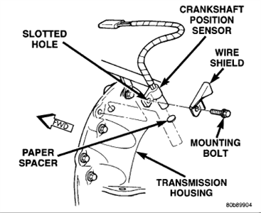
The Crankshaft Position Sensor (CKP) is mounted to the transmission bellhousing at the left/rear side of the engine block...

9_21_2011_12_48_19_pm.jpg


9_21_2011_12_48_47_pm.gif

Inatallation: 4.0L Engine
New replacement sensors will be equipped with a paper spacer glued to bottom of sensor. If installing (returning) a used sensor to vehicle, a new paper spacer must be installed to bottom of sensor. This spacer will be ground off the first time engine is started. If spacer is not used, sensor will be broken the first time engine is started.

New Sensors:
Be sure paper spacer is installed to bottom of sensor. If not, obtain spacer PN05252229.

Used Sensors:
Clean bottom of sensor and install spacer PN05252229.
  1. Install sensor into transmission bellhousing hole.
  2. Position sensor wire shield to sensor.
  3. Push sensor against flywheel/drive plate. With sensor pushed against flywheel/drive plate, tighten mounting bolt to 7 Nm (60 inch lbs.) torque.
  4. Route sensor wiring harness into wire shield.
  5. Connect sensor pigtail harness electrical connector to main wiring harness.
Hope helps (remember to rate and comment this free answer).
2helpful
1answer

I have a code P320 on my 1999 Jeep Grand. What do I need to replace and how? Thanks for your help. John

Replace the crank sensor.


360dreamworx_25.gif
The Crankshaft Position (CKP) sensor is mounted to the transmission bellhousing at the left/rear side of the engine block. The sensor is adjustable and is attached with one bolt. A wire shield/router is attached to the sensor.

REMOVAL
  1. Disconnect sensor pigtail harness (3-way connector) from main engine wiring harness.
  2. Remove sensor mounting bolt.
  3. Remove wire shield and sensor.
INSTALLATION
New replacement sensors will be equipped with a paper spacer glued to bottom of sensor. If installing (returning) a used sensor to vehicle, a new paper spacer must be installed to bottom of sensor. This spacer will be ground off the first time engine is started. If spacer is not used, sensor will be broken the first time engine is started.
  1. New Sensors: Be sure paper spacer is installed to bottom of sensor. If not, obtain spacer PN05252229.
  2. Used Sensors: Clean bottom of sensor and install spacer PN05252229.
  3. Install sensor into transmission bellhousing hole.
  4. Position sensor wire shield to sensor.
  5. Push sensor against flywheel/drive plate. With sensor pushed against flywheel/drive plate, tighten mounting bolt to 7 Nm (60 in. lbs.) torque.
  6. Route sensor wiring harness into wire shield.
  7. Connect sensor pigtail harness electrical connector to main wiring harness.
0helpful
1answer

CRANK SHAFT SENSOR

To remove the sensor:
  • Disconnect the wiring harness.
  • Unbolt the sensor mounting bolt.
If the crankshaft timing sensor or the camshaft reference sensor is removed, follow this procedure when the sensor is replaced:
  • Thoroughly clean the sensor tip and install a new spacer on the sensor tip. New sensors should be supplied with the spacer installed.
fr_24.15.gif Spacer on crankshaft timing sensor and camshaft position sensor.
  • Install the sensor until the spacer lightly touches the sensor ring, and tighten the sensor mounting bolt 105 in.lb.
0helpful
1answer

Where are the bolts to remove the starter on a 1993 quad 4 grand am?

REMOVAL & INSTALLATION
Except 2.3L and 2.4L Engines

  1. Disconnect the negative battery cable.
  2. Raise and safely support the vehicle. Disconnect the electrical wiring from
    the starter, if accessible.
  3. If necessary for access, unfasten the three dust cover bolts, then pull the
    dust cover back to get to the front starter bolt. Remove the front starter bolt.

  4. Remove the rear support bracket.
  5. Pull the rear dust cover back (if applicable) to gain access to the rear
    starter bolt and remove the rear bolt.
  6. Note the number and location of any shims.
  7. Push the dust cover back into place (if removed), then lower the starter
    (disconnect any wiring if previously inaccessible) from the vehicle.
    To install:

  8. Position the starter in the vehicle, connect the wiring, then install the
    rear starter bolt.
  9. Install the front starter bolt, then tighten both bolts to 32 ft. lbs. (43
    Nm)
  10. If removed, install the dust cover and the rear support bracket.
  11. Connect the electrical wiring to the starter, if not already attached.
  12. Carefully lower the vehicle, then connect the negative battery cable.


    Fig. 1: Once the vehicle is raised and safely supported, you
    will be able to see the starter motor
    86883015.jpg


    Fig. 2: After disconnecting the wiring, remove the starter
    mounting bolts
    86883016.jpg


    Fig. 3: When removing the starter, be sure to note the number
    and location of any shims
    86883017.jpg


    Fig. 4: View of the starter mounting - 3.1L and 3.3L engines
    91062g09.gif

2.3L Engine
1988-89 (VIN D)

  1. Disconnect the negative battery cable.
  2. Remove the air cleaner to throttle body duct.
  3. Label and detach the TPS, IAC and MAP sensor connectors.
  4. Remove vacuum harness assembly and the MAP sensor vacuum hose from intake
    manifold, then position aside.
  5. Unfasten the cooling fan shroud attaching bolts, then remove the shroud
    (including the MAP sensor).
  6. Remove the coolant fan-to-upper radiator support bolt, then unfasten the
    remaining upper radiator support bolt and the upper radiator support.
  7. Detach the connector from the cooling fan.
    NOTE: Because of the low clearance, be very careful not to
    damage the TPS lock tang with the fan bracket.


  8. Lift the fan assembly out of the two lower insulators. Rotate the bracket so
    the two lower bracket legs point upward. Move the fan assembly toward the left
    (drivers) side until the fan blade overlaps the radiator tank-to-core seam about
    1 inch (25mm). Lift the fan assembly from the engine compartment.
  9. Remove the harness retaining clip from the engine mount bracket stud.
    Unfasten the starter mounting bolts.
  10. Tilt the rear of starter towards the radiator, pull the starter out, then
    rotate solenoid towards the radiator to gain access to the electrical
    connections.
    NOTE: Be careful not to damage the crank sensor mounted
    directly to the rear of the starter. If it gets damaged, it must be replaced.


  11. Detach the electrical connectors from the solenoid.
  12. Move the starter toward the driver's side of the vehicle, then lift it from
    the vehicle.
    To install:

  13. Insert the starter between the throttle body and the air cleaner housing,
    then move it toward the right (passenger) side.
  14. Attach the solenoid electrical connectors. Make sure to properly position
    the plastic guard over the stud and nut for the battery cable.
  15. Rotate the starter into the proper position, install any shims that were
    removed and secure using the mounting bolt. Tighten the bolts to 74 ft. lbs.
    (100 Nm).
  16. With the fan's bracket two lower legs facing upward, place the fan assembly
    between the throttle body and the radiator while overlapping the radiator
    tank-to-core seam with the fan blade by about 1 inch (25mm). Be careful not to
    damage the lock tang on the TPS.
  17. Rotate the fan bracket, then place the two lower legs into the insulators.
  18. Attach the electrical connector to the cooling fan.
  19. Install the upper radiator support and the coolant fan should, then install
    the fan-to-upper radiator support mounting bolt.
  20. Connect the MAP vacuum hose and the vacuum harness assembly to the intake
    manifold.
  21. Attach the TPS, IAC and MAP sensor connectors.
  22. Install the air cleaner to throttle body duct.
  23. Connect the negative battery cable, then check for proper starter operation.

1990-95 (VIN D), 1989-94 (VIN A), 1992-94 (VIN 3)

  1. Disconnect the negative battery cable.
  2. If necessary for access, remove the air induction tube.
  3. Detach the coolant fan electrical connector, then remove the fan assembly.
  4. Remove the oil filter, if necessary for access to the starter.
  5. For vehicles through 1990, remove the intake manifold brace.
  6. Remove the mounting bolts; some engines may have 3 starter mounting bolts.
    Pull the starter out of the hole and move toward the front or passenger side of
    the vehicle.
  7. Disconnect the wiring from the solenoid.


    Fig. 5: Starter mounting for 2.3L engine - 1990-95 models
    91062g10.gif

  8. Remove the starter by lifting it between the intake manifold and the
    radiator.
    To install:

  9. Lower the starter between the intake manifold and the radiator, then connect
    the wiring to the solenoid.
  10. Rotate the starter into installation position and install the mounting
    bolts. For vehicles through 1994, tighten to 74 ft. lbs. (100 Nm). For 1995
    vehicles, tighten the bolts to 32 ft. lbs. (43 Nm).
  11. If equipped, install the intake manifold brace and oil filter, if removed.
  12. Install the cooling fan assembly, then attach the electrical connector.
  13. If removed, install the air induction tube.
  14. Connect the negative battery cable and check the starter for proper
    operation.

2.4L Engine

  1. Disconnect the negative battery cable.
  2. Remove the air inlet duct attached to the throttle body.
  3. Remove the top starter bolt.
  4. Raise and safely support the front of the vehicle securely on jackstands.
  5. Remove the lower starter bolt.
  6. Position the engine wiring harness aside.
  7. Position the starter for access to solenoid wiring.
  8. Remove the wiring attached to the starter.
  9. Carefully lower the starter.
    To install:

  10. Attach the wiring to the starter and position the assembly into place.
  11. Install the lower starter bolt.
  12. Reposition the wiring.
  13. Lower the vehicle and install the upper starter bolt. Tighten the bolts to
    66 ft. lbs. (90 Nm).
  14. Attach the air inlet duct to the throttle body.
  15. Connect the negative battery cable.


prev.gif next.gif
1helpful
1answer

Where Are The sensor Banks On The 2004 GC

Grand Cherokee oxygen sensor locations for 4.0 and 4.7 engines

510d5d9.jpg


f8b5293.jpg


Four wires (circuits) are used on each O2 sensor:

  • 12–volt feed circuit for the sensor heating element
  • Ground circuit for the heater element
  • Low-noise sensor return circuit to the PCM
  • Input circuit from the sensor back to the PCM to detect sensor operation

O2S Sensor removal Never apply any type of grease to the oxygen sensor electrical connector, or attempt any soldering of the sensor wiring harness.
WARNING: THE EXHAUST MANIFOLD, EXHAUST PIPES AND CATALYTIC CONVERTER(S) BECOME VERY HOT DURING ENGINE OPERATION. ALLOW ENGINE TO COOL BEFORE REMOVING OXYGEN SENSOR.
1. Raise and support vehicle.
2. Disconnect O2S pigtail harness from main wiring harness.
3. If equipped, disconnect sensor wire harness mounting clips from engine or body.
CAUTION: When disconnecting sensor electrical connector, do not pull directly on wire going into sensor.
4. Remove O2S sensor with an oxygen sensor removal and installation tool.

02S Sensor installation
Threads of new oxygen sensors are factory coated with anti-seize compound to aid in removal. DO NOT add any additional anti-seize compound to threads of a new oxygen sensor.
1. Install O2S sensor. Tighten to 22 ft. lbs. (30 N·m) torque.
2. Connect O2S sensor wire connector to main wiring harness.
3. If equipped, connect sensor wire harness mounting clips to engine or body. When Equipped: The O2S pigtail harness must be clipped and/or bolted back to their original positions on engine or body to prevent mechanical damage to wiring.


Hope thats help (remember comment and rated this).
0helpful
1answer

What dose the crank sensor look like and where dose it go on a 99 dodge dokota

Please don't forget to rate!


  1. Remove the air cleaner assembly if necessary for access to the sensor.
  2. Disconnect the pigtail harness from the sensor.
  3. Remove the nut holding the sensor wire clip to the fuel rail mounting stud.
  4. Remove the sensor mounting hardware, then the sensor.
  5. Remove the clip from the sensor wire harness.
To install:
  1. Install the sensor flush against the opening.
  2. Install and tighten the bolts or nuts, as applicable.
  3. Install the electrical connector.
  4. Install the clip on the sensor wire harness.
  5. Install the clip over the fuel rail mounting stud. Install the clip mounting nut.

These 4 pictures are for the Automatic:


672b280.jpg

f025658.jpg

24a1c5a.jpg

These are for a manual trans:


fc2c89c.jpg

41a22c0.jpg

ba33907.jpg
0helpful
1answer

Speed sensor

The step by step procedure is given below

  1. Park your Honda Accord on a level surface, make sure the ignition is off, activate the emergency brake and place blocks behind the back tires for safety. Disconnect the negative battery cable with a terminal puller.
  2. Raise the vehicle on the side of the wheel speed sensor's location. Remove the wheel and tire assemblies.
  3. Disconnect the sensor harness connector. At the connector end, remove the grommets, clips or retainers in order to detach the harness. Take note of where these connect in order to install the new sensor correctly.
  4. Unscrew the speed sensor mounting bolt and remove the sensor from the vehicle.
  5. Obtain the new speed sensor and install it in the differential housing, with the retaining bolt loosely tightened.
  6. Use the white line on the wires as a guide and route the wiring harness without twists or crimps. Then torque the mounting bolt to 7.2 foot pounds (9.8 Nm).
  7. Start at the sensor end and, working your way to the connector end, attach all the clips, retainers and grommets as observed during removal. Connect the sensor wire.
  8. Lower the vehicle safely and reconnect the negative battery cable. Refer to your owner's manual to perform an ABS system check to confirm that you installed the sensor properly.
0helpful
1answer

Noise comiming from around fan mount

you need a new fan, is it the inside fan for the heaters? or the main cooling fan? is the engine vertical or stright? if its a vertical engine then it will be quite a big belt around the fan, sort this quickly if so, as can cause alot of damage if the belt snaps.
0helpful
1answer

Need to attach new electric temp. switch/sensor where aftermarket mechanical one is installed

The factory wire to the factory gauge is a solid green wire. that year truck the sending unit usually mounted in the drivers side cylinder head but i have seen some in the passanger side if they have cut the wire and you can goto the main harness connector under the brake master cylinder and booster and find the only solid dark green wire and follow it forward to see how far it back they cut then just splice and run it to your new sending unit . If you want to check to make sure the gauge works after you find the solid green wire put it to a ground and the gauge should go to hot if it does not you have a bad gauge or a cluster wireing in side the truck and that is why they put the aftermarket gauge in .
1helpful
1answer

I need some info on the were abouts,and how much im gittin in over my head with changein the crankshaft positioning sensor on my 1994 lexus LS 400?

It's not too bad of a project. Your CPS (Crankshaft Position Sensor) is located in the engine compartment, front engine area / driver's side, mounted in the engine block above the crankshaft pulley. I've provided a photo below to give you a better idea of what your looking for.

5c959ad.jpg
To remove the CPS, simply disconnect the wire harness and remove the mounting bolt. From there, the CPS should slide right out.

When installing your new CPS, make sure to check the tip to ensure it came with a new spacer (will be attached to the tip). Thereafter, install the sensor until the spacer lightly touches the sensor ring. Tighten the sensor mounting bolt to approximatley 105 in.lb. and attach the wire harness.

Help this helps and good luck!
Not finding what you are looking for?

43 views

Ask a Question

Usually answered in minutes!

Top Ford Experts

ZJ Limited
ZJ Limited

Level 3 Expert

17989 Answers

Ronny Bennett Sr.
Ronny Bennett Sr.

Level 3 Expert

6988 Answers

Thomas Perkins
Thomas Perkins

Level 3 Expert

15088 Answers

Are you a Ford Expert? Answer questions, earn points and help others

Answer questions

Manuals & User Guides

Loading...