1991 Toyota Land Cruiser Logo
Anonymous Posted on Apr 24, 2009

80 series 1991 toyota landcruiser have no interior lights checked all fuses not blown and cant find ignition switch lamp relay any ideas were to find relay

1 Answer

Anonymous

Level 1:

An expert who has achieved level 1.

Mayor:

An expert whose answer got voted for 2 times.

  • Contributor 1 Answer
  • Posted on Sep 25, 2009
Anonymous
Contributor
Level 1:

An expert who has achieved level 1.

Mayor:

An expert whose answer got voted for 2 times.

Joined: Sep 25, 2009
Answers
1
Questions
0
Helped
905
Points
2

I am chasing the exact same problem. I have put it down to no power feed past dome fuse no8 the light gauge wire, blue/yellow trace is under stress behind the heater box and can break internally. I think mine is broken between fuse 8 and inside the car, as there is no continuity between the two points on my vehicle, and there is on my brothers car, same car

Add Your Answer

×

Uploading: 0%

my-video-file.mp4

Complete. Click "Add" to insert your video. Add

×

Loading...
Loading...

Related Questions:

0helpful
2answers

Por favor, necesito diagrama de caja de fusibles para Mazda B2300 del 2001

Mazda B-Series (2001) - fuse box diagram Year of production: 2001
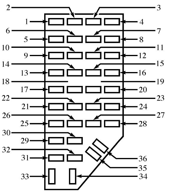
Interior fuse panel

Mazda B-Series - fuse box -
interior fuse panel Number Ampere rating [A] Description 1 5 Power Mirror 2 10 Blower Motor Relay, Air Bag Diagnostic Monitor, Passive Deactivation (PAD) Module 3 7,5 Trailer Tow Connector (LH Stop/Turn) 5 10 4×4 Control Module 7 7,5 Trailer Tow Connector (LH Stop/Turn) 9 7,5 Stoplamp Switch 10 7,5 Cruise Control Servo/Amplifier Assy., GEM/CTM, Shift Lock Actuator, Blend Door Actuator, A/C Heater Control Assy., Turn Signals 11 7,5 Instrument Cluster, Main Light Switch, RABS Resistor 13 20 Brake Pedal Position Switch 14 20 RABS Module 10 4WABS Mod., 4WABS Main Relay 16 30 W/W Motor, Wiper Hi-Lo Relay, Wiper Run/Park Relay, Washer Pump Relay 17 25 Cigar Lighter, Data Link Connector (DLC) 19 25 PCM Power Diode, Ignition, PATS 20 7,5 GEM/CTM, Radio 21 20 Flasher 22 20 Auxiliary Power Point 24 7,5 Clutch Pedal Position (CPP) Switch, Starter Interrupt Relay 26 10 Battery Saver Relay, 4×4 Electronic Shift Relay, Interior Lamp Relay, 4×4 Elec. Shift Control Module, Dome/Map Lamp, Instrument Illumination Dimming Module, Restraint Control Module, GEM/CTM, Instrument Cluster 28 7,5 GEM/CTM System, Radio 29 15 Radio 33 15 Headlights, DRL Module, Instrument Cluster 35 15 ISA Horn Relay if not Equipped with Truck Security Module

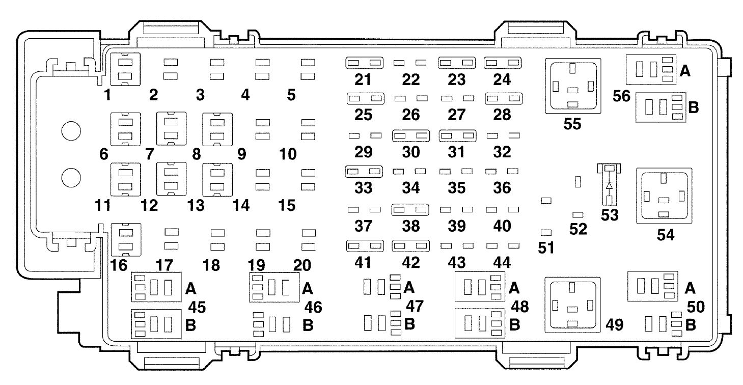
Engine compartment fuse block

Mazda B-Series - fuse box -
engine compartment Number Ampere rating [A] Description 1 50 I/P Fuse Panel 6 50 ABS Pump Motor 7 30 Powertrain Control Module 8 20 Power Door Locks and Remote Entry 11 50 Starter Relay Ignition Switch 12 10 PCM Memory 13 20 4×4 Motor 16 40 Blower Motor 21 10 PCM Memory 23 20 Fuel Pump Motor 24 30 Headlights 25 10 A/C Clurtch 28 30 4WABS Module 30 15 Trailer Tow 31 20 Fog Lamps, Day Time Running Lamps (DRL) 33 15 Park Lamp 38 10 Left Headlamp Low Beam 41 - Heated Oxygen Sensors 42 10 Right Headlamp Low Beam 45A - Wiper High/Low 45B - Wiper Park/Run 46A 46B - Front Washer Pump 47A 48A - Fog Lamp 48B - Fog Lamp Relay 49 - Full Starter 50A 50B - Fuel Pump 53 - Powertrain Control Module (PCM) Diode 54 - Powertrain Control Module (PCM) Diode 55 - Blower 56A - A/C Clutch Solenoid 56B - Trailer Tow
2helpful
2answers

Where is the interior light relay on 2001 ford windstar

Your interior lights are controlled by the GEM - generic electronic module !
Battery Saver The battery saver relay is controlled by the generic electronic module (GEM) and is located in the fuse junction panel. The battery saver relay is designed to supply B+ voltage to the following:
  • dome and map lamp switches
  • visor lamps
  • glove box lamp switch
  • interior lamp switch
  • interior courtesy lamp relay
  • delayed accessory relay
The function of the battery saver relay is to prevent excessive battery drain by interior lighting circuits. The GEM supplies a ground signal to the battery saver relay anytime one of the wake-up inputs of the GEM is activated to operate the battery saver relay. A wake-up command is sent when:
  • any door becomes ajar or is opened or closed.
  • the ignition key is inserted or removed.
  • the ignition switch is turned from OFF to RUN.
  • the ignition switch is turned from OFF to ACC.
  • a wake-up request is received from the remote anti-theft personality (RAP) module (if equipped).
  • The GEM will maintain the ground input with ignition in RUN or for 40 minutes from the last input activation with ignition in the OFF position. After 40 minutes the ground signal is discontinued.
This de-engergizes the battery saver relay preventing B+ voltage supply to the controlled switches and circuits.
  • Courtesy Lamp On Continuously
  • Short to power.
  • Damaged switch.
  • Generic electronic module.
  • GO to Pinpoint Test AF .
PINPOINT TEST AF: COURTESY LAMPS ON CONTINUOUSLY AF1 PRELIMINARY CHECKS
  • Check connections for clean tight fit.
  • Check for loose or damaged wires.
Do components and wiring check OK? Yes No GO to AF2 . SERVICE or REPLACE as required. GO to AF2 . AF2 CHECK CIRCUIT 53 (BK/LB)
  • Remove interior lamp relay.
  • Measure voltage at interior lamp relay connector Pin 87, Circuit 53 (BK/LB).
Is voltage greater than 0 volts? Yes No SERVICE Circuit 53 (BK/LB) for short to B+. RESTORE vehicle. RETEST system. GO to AF3 . AF3 CHECK CIRCUIT 434 (LB/BK)
  • Measure resistance between interior lamp relay connector Pin 85, Circuit 434 (LB/BK) and ground.
Is resistance 5 ohms or less? Yes No SERVICE Circuit 434 (LB/BK) for short to ground. RESTORE vehicle. RETEST system. REPLACE interior lamp relay. RESTORE vehicle. RETEST system. Interior lamp relay is located in the Instrument panel fuse box .
I/P Fuse Panel (Located Below Driver's Side of I/P )
0helpful
1answer

1996 80 series landcruiser no low beams high beams are fine no spotties all work when pushed into high beams exept spotties and no high beam light shown on dash... Fuses all good blown relay that fused...

Hi Grant I believe that the fuses you are looking for are 7.5 amps and they are found in the fuse cabinet under the hood. If that fails try replacing the H4 bulbs, which I'm susspecting may have blown! Regards John
0helpful
1answer

Toyota Landcruiser 1991 80 series had a clunk when you change gears??

CHECK FOR LOOSE DRIVE SHAFT BOLTS OR YOU COULD HAVE WORN UNIVERSAL JOINT BEARINGS.
1helpful
2answers

I have an 80 series landcruiser with A442F transmission, built 1993. It will not select 1st gear or overdrive. It takes off in 2nd and shifts to 3rd normally, 1st gear can be selected manually and changes...

It seems like your "2nd start" button is turned on. The 80 series LC has a button next to the shifter which allows it to start in 2nd gear. If the button is not engaged then there could be a problem with the circuit, but that is not common
0helpful
2answers

Broken sub tank switch in 80 series toyota landcruiser

Replace it. Most switches are mounted to plastic snap clips than can be removed with a simple Flathead screwdriver.A $5 plastic pry tool set is the best, but a butter knife or two works wonders sometimes.
4helpful
2answers
1helpful
1answer

Fuse or what

Your multifunction switch on the steering column controls your exterior lights. The GEM module controls the interior lights and other stuff. If bad, it would not blow fuses. WHich fuse blows?
Your Ford dealer might be familiar with this issue, so call the service dept and ask them and get a quote. It may be wiring.
reoprt back.

  • The high beams are inoperative
  • Circuitry.
  • Multifunction switch.
  • Go To Pinpoint Test C .


--------------------------------------------------------------
Principles of Operation
Generic Electronic Module (GEM) The generic electronic module (GEM) receives inputs from the following:
  • door ajar switches
  • liftgate ajar switch (wagon)
  • liftgate glass switch (wagon)
  • headlamp switch
  • keyless entry keypad switches
  • the powertrain control module (PCM) (vehicle speed signal)
  • ignition switch
  • remote keyless entry transmitter
The GEM uses these inputs to control the output to the battery saver relay and interior lamp relay. Both relays are integral to the central junction box (CJB) and cannot be accessed directly.
Interior Lighting Systems The GEM grounds the battery saver relay and interior lamp relay coils when any door ajar switch or the headlamp switch is closed. The interior lamp relay then supplies power to the interior lamp circuit. Vehicle speed must be less than 15 kph (9 mph) for the GEM to ground the interior lamp relay. The interior lamps will remain illuminated for a period of up to 25 seconds after all doors are closed or until the ignition is switched from the OFF position, or the GEM receives a vehicle speed signal. Actuating the interior lights from the headlamp switch will operate at any time.
Illuminated Entry Illuminated entry is activated when a keyless entry keypad switch provides ground on the GEM input or when the GEM receives an unlock signal from the remote keyless entry key fob. The GEM then provides ground to the battery saver and interior lamp relay coils. Illuminated entry is deactivated when the GEM receives a lock signal from the remote keyless entry key fob or if the GEM receives ground inputs from the keyless entry keypad switch lock code. Illuminated entry will also be deactivated when the GEM receives input voltage from the ignition switch.
Battery Saver The battery saver is activated when the GEM is not receiving voltage input from the ignition switch (off position). The GEM will then provide ground to the battery saver relay coil for a maximum of 30 minutes depending on the state of the interior lamp switch inputs to the GEM. The energized battery saver relay switches voltage to the demand lamp circuit and the interior lamp relay coil. After time-out, the GEM removes ground to the battery saver relay disabling the demand lamp circuit.
Puddle Lamps The puddle lamp relay operates reverse from the battery saver relay and the interior lamp relay. The puddle lamp relay coil receives voltage when the ignition switch is in the START or RUN position, which disables the circuit to the puddle lamps.
Inspection and Verification
  1. Verify the customer concern by operating the system.
  1. Visually inspect for obvious signs of mechanical and electrical damage.


Visual Inspection Chart Electrical
  • Battery junction box (BJB) fuse 101 (60A)
  • Central junction box (CJB) fuse 226 (10A)
  • Bulb(s)
  • Central junction box (CJB)
  • Generic electronic module (GEM)
  • Connectors
  • Circuitry


0helpful
1answer

How to change the headlight on a 1991 toyota landcruiser

you should be able to take the light out from the front after removing the grille and headlight surround, this is if it what we call in Australia a "80 series" landcruiser.
Not finding what you are looking for?

915 views

Ask a Question

Usually answered in minutes!

Top Toyota Experts

ZJ Limited
ZJ Limited

Level 3 Expert

17989 Answers

Thomas Perkins
Thomas Perkins

Level 3 Expert

15088 Answers

ROBERT GARCIA
ROBERT GARCIA

Level 3 Expert

926 Answers

Are you a Toyota Expert? Answer questions, earn points and help others

Answer questions

Manuals & User Guides

Loading...